Magnum Venus Plastech HIS INSTRUCTION MANUAL User Manual
Page 27
- 27 - H.I.S. Instruction Manual
Gun Assembly Instructions
The gun assembly procedure, as described, is the factory recommended method. MVP will
not be responsible for any damage to unit if the recommended procedure is not followed.
Components are first assembled to form subassembly units. The subassemblies are in
turn assembled to complete gun assembly. This procedure simplifies the assembly
process.
This assembly applies for all HIS ’80 gun systems (Chopper, Gelcoat, Casting, Saturator or
Hydrajector). The exploded drawings should be used in conjunction with these instructions.
CAUTION: Do not lubricate any part of this assembly that comes into contact with MEKP.
Gun Head Subassembly (’80 Model)
1. With gun head place in vise (nozzle end up), drop flush seat into nozzle opening.
Very gently tap seat down until it bottoms out in nozzle chamber. Do not distort
seat. Use appropriate wooden dowel. See instruction sheet on page 32 item 4.
2. Insert flush seat retainer into nozzle opening of gun head. Use ST63 (45027-1)
flush retainer puller (in repair kit) to insert retainer. Drive retainer firmly down
against flush seat; make sure side holes in retainer align with side holes in gun
head. Unscrew puller after retainer is installed.
3. Place ST70 (45030-1)
rod in vise with approximately 2” of rod sticking above vise.
Drop flush needle (threaded end first) through nozzle opening on gun head.
Holding threaded end of flush needle, place needle and gun head down on top of
ST70 (45030-1) tool in vise.
4. Using ST27 (45015-1) packing tool in tool kit, push flush retainer onto threaded
need of flush needle and down into flush chamber of gun head until retainer
bottoms out.
5. Slide one set of packing over flush needle and push down in place using ST27
(45015-1) packing tool (see instruction below).
Note: Install packing one piece at a time; 5 pieces of packing = 1 set.
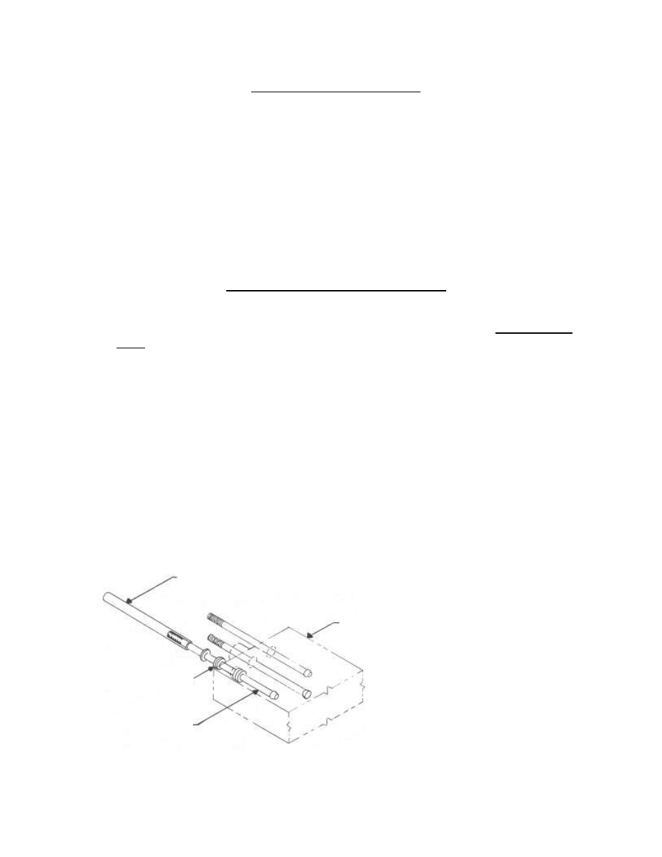
Packing installation tool (45015-1)
Gun Block
Needle
Packing Set (5 pc. Set)
NEEDLE PACKING INSTALLATION DIAGRAM