Lap pad calibration & set-up – Liquid Controls LCR Setup & Operation User Manual
Page 25
25
Lap Pad Calibration & Set-up
MULTI-POINT CALIBRATION CONTINUED
Step 5:
Refill the prover at the same flow rate as S tep 4 to verify that the meter remains within tolerance
limits. Assuming that the data provided by the meter manufacturer is correct, and that proper technique
was used for selecting and entering the multi-point table, it should be possible to fill the prover at any
flow rate within the linearized range and obtain an error near zero.
2. FIELD PROVING TECHNIQUE
When the meter's accuracy is not provided by the manufacturer , points to enter into the multi-point calibration table
need to be determined by field proving at various flow rates.
Step 1:
Start a proving run of the meter while viewing PRODUCT CALIBRATION - Screen 3 at the normal high
flow rate of the system while the LINEAR^ field is in the SETUP mode. With the prover full, press
PRINT
and adjust the PULSES/UNIT by entering the actual PROVER QTY (see Page 22).
Step 2:
Go to of PRODUCT CALIBRATION - Screen 7. With PT^ set to 1 and LINEAR^ still set to SETUP,
start a new prover run at the same flow rate as Step 1. During prover filling, note the maximum RATE
that is displayed. When the prover is filled, press PRINT. Advance to PRODUCT CALIBRATION -
Screen 8. Enter the volume delivered to the prover in PROVER QTY. The %ERROR field will then
display the calculated error for that rate. This should be a very small value since Step 1 "zeroed" the
meter at the same rate. Return to PRODUCT CALIBRATION - Screen 7 and enter the maximum flow
rate observed during prover filling in RATE for PT^ 1.
Step 3:
With PT^ set to the next point and LINEAR^ still set to SETUP, start a prover run at a dif ferent flow
rate. During prover filling, note the maximum RATE that is displayed. When the prover is filled, press
PRINT
. Advance to PRODUCT CALIBRATION - Screen 8. Enter the volume delivered to the prover in
PROVER QTY
. The %ERROR field will then display the calculated error for that rate. Return to
PRODUCT CALIBRATION
- Screen 7 and enter the maximum flow rate observed during prover filling
in RATE for that PT^.
Step 4:
Continue proving at other flow rates using additional PT^ numbers following the same procedure as
Step 3. A minimum of three points is recommended (high, medium and low flow) to obtain a good fit to
the curve. All ten points can be used to obtain optimum result s. Any unused points should be left at
RATE=0
and %ERROR=0.
1
2222.000000
0.000
GALLONS
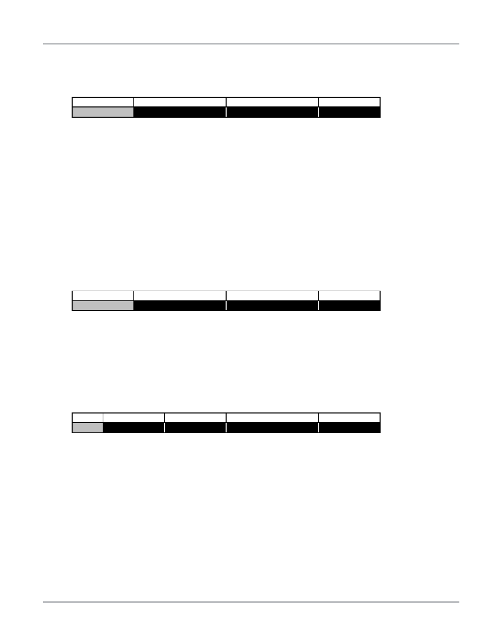
Product Calibration - Screen 3
#^
PULSE/UNIT
PROVER QTY
UNITS
1
2222.000000
0.000
GALLONS
Product Calibration - Screen 3
#^
PULSE/UNIT
PROVER QTY
UNITS
PT^
1
0.00
GALLONS
PER MINUTE
0.000
Product Calibration - Screen 7
RATE
UNITS^
RATE BASE^
%ERROR