8 connect probes to the sc1000 controller, 1 connect the probe data cable, Installation – Hach-Lange SC 1000 User Manual
Page 45
43
Installation
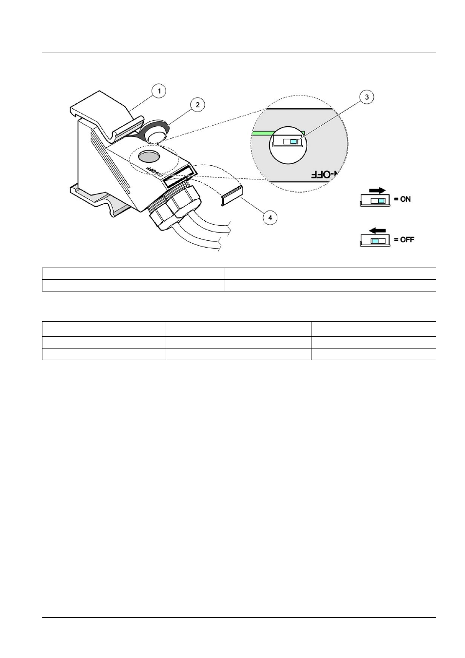
Note: The DIP switch can also be operated when the connector is fitted. The OFF and ON switch
positions are also printed on the connector housing. Use the switch for commissioning and
troubleshooting segment by segment. Shut down the segments one by one and check for function
and errors.
3.8 Connect probes to the sc1000 controller
All sc series probes can be used on the sc1000 controller.
Important Note: Plan the route for the probe cable and lay the data and power cables so
that they do not cause a trip hazard and the cables do not have any sharp bends.
For details on the installation and operation of the probe, refer to the appropriate probe
manual.
3.8.1 Connect the probe data cable
1. Unscrew the protective cover on the controller socket (
). Retain the
protective cover. When you remove the probe, re-fit the protective cover.
2. Align the connector plug with the socket, pay attention to the orientation of the
connector lugs.
3. Hand-tighten the union nut.
Note: Keep the middle connection of the probe module free. Use the free port to connect the display
module to each probe module in a network.
Figure 33 Setting a terminating resistor (DIP switch in the connector)
1
Housing, network connector
3
Dip switch (note position assignments as shown)
2
Cap, rubber
4
Insert, plastic label
Table 12 Communication connector terminating resistor (communication termination)
Switch setting
Terminating resistors
Connection 2
On
Enabled
Disabled
Off
Disabled
Enabled