4 modbus card connections, Figure 23, Installation – Hach-Lange SC 1000 User Manual
Page 35
33
Installation
5. Write the serial number from the rating plate on the supplied sticker and attach it to
the main high voltage barrier (
6. Install the probe module cover.
After installation and connection of a plug-in expansion card, the card must be configured
to the system. For output card setup instructions, refer to
3.6.4 Modbus card connections
Modbus RS485 (YAB021) and Modbus RS232 (YAB047) are available. For more detailed
information refer to the bus system manual.
To make a Modbus card connection:
1. Remove power from the instrument. Remove the probe module cover.
2. Connect the Modbus card to the appropriate slot (
). Use a magnetic
screwdriver to secure the four screws to the card.
3. Install the card connector to the appropriate connection on the main circuit board
(
Figure 17
).
4. Feed the cable through the base of the module and properly prepare and insert each
wire into the terminal according to
Figure 24
/
and
Figure 25
/
Table 8
.
5. Write the serial number from the rating plate on the supplied sticker and attach it to the
main high voltage barrier (
).
6. Install the probe module cover.
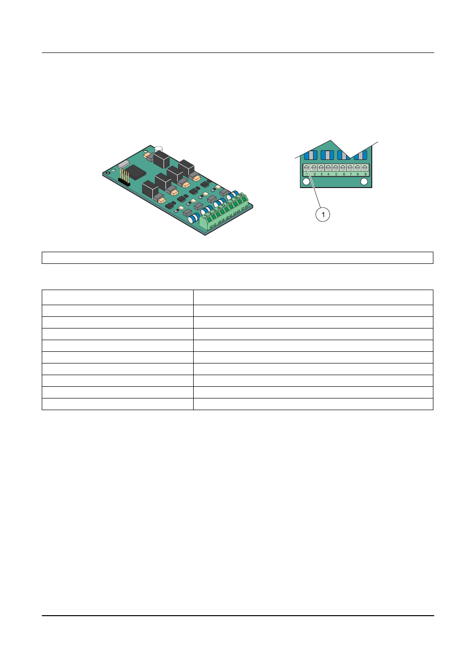
Figure 23 Output card (YAB019) cable connections
1
Terminal Block
–
Refer to
Table 6
for terminal assignments.
Table 6 Output card (YAB019) terminal assignments
Terminal
Designation
1
Output 1+
2
Output 1 –
3
Output 2 +
4
Output 2 –
5
Output 3 +
6
Output 3 –
7
Output 4 +
8
Output 4 –
9
Shield (Connected to protective earth)