Figure 7, Installation – Hach-Lange SC 1000 User Manual
Page 19
17
Installation
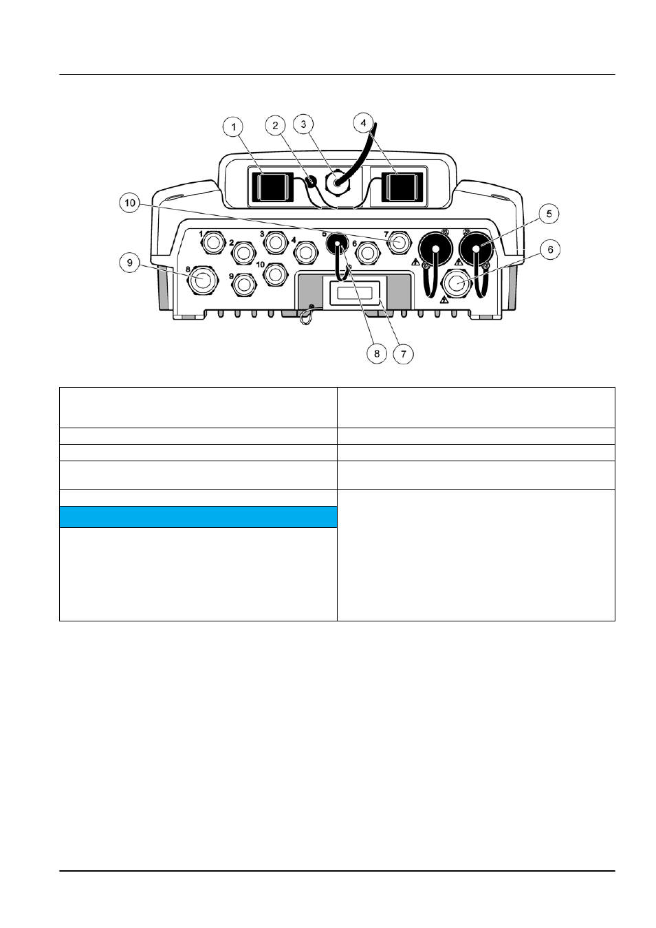
Figure 7 Housing breakouts
1
Storage card slot
6
AC power connection (PS1), strain relief M20 × 1.4 mm
(4–8 mm cable diameter), conduit, different version of
power cord (optional)
2
GSM antenna connection (optional)
7
Network interface
3
Cable assembly for connection to probe module
8
Cable assembly for connection to display module
4
Service port
9
Relay connection—2.19 mm for conduit or strain relief
M20 × 1.5 with union mount (9–13.5 mm cable diameter)
5
Power outlet for 100–240 VAC powered sc probes
10 Configured as either sc probe connectors or
strain-reliefs, M16 × 1.5 (5–6 mm cable diameter)
N o t i c e
Please observe the output voltage at the sockets.
The output voltage supplied by the sc controller to the
sockets corresponds to the country-specific mains voltage to
which the controller is connected.
Never connect consumers with a lower input voltage to the
sc controller if the sc controller is operated with a higher
mains voltage.
- AMTAX sc (118 pages)
- PHOSPHAX sc (106 pages)
- CL17 Instruction sheet (8 pages)
- CL17 USER MANUAL (60 pages)
- CLF10 sc (382 pages)
- 9184 sc (50 pages)
- POLYMETRON 9611 sc Installation (398 pages)
- POLYMETRON 9610 sc Maintenance and Troubleshooting (286 pages)
- POLYMETRON 9611 sc USER INSTRUCTIONS: SEQUENCER LINE INSTALLATION (2 pages)
- POLYMETRON 9611 sc USER INSTRUCTIONS: SS SAMPLE CONDITIONING (4 pages)
- HACH 5500 sc Installation (408 pages)
- HACH 5500 sc Maintenance and Troubleshooting (286 pages)
- HACH 5500 sc PO43-HR Operations (390 pages)
- HACH 5500 sc PO43-LR Operations (392 pages)
- HACH 5500 sc SiO2 Installation (418 pages)
- HACH 5500 sc SiO2 Operations (394 pages)
- POLYMETRON 9610 sc SiO2 Installation (410 pages)
- POLYMETRON 9240 Basic User Manual (162 pages)
- POLYMETRON 9240 Operator Manual (144 pages)
- PHOSPHAX sigma Basic User Manual (305 pages)
- AMTAX inter2 Basic User Manual (377 pages)
- GANIMEDE P (60 pages)
- BODTrak II Basic User Manual (172 pages)
- BODTRACK II User Manual (28 pages)
- BODTRAK II: Respirometric Biochemical Oxygen Demand (BOD) (46 pages)
- SPECTRO COLOR d-8 (29 pages)
- REFO 60_REFO 60D (36 pages)
- REFO 3_REFO 3D (19 pages)
- LICO 620 Basic User Manual (329 pages)
- LICO 620 User Manual (114 pages)
- SD900 (2 pages)
- LZX971 (8 pages)
- SC Sensor Plug and SC Sensor Coupling (8 pages)
- HQ Series Portable Meters (4 pages)
- LDO Sensor Replacement Kit for use with Hach HQ10 and HQ20 (43 pages)
- LDO Sensor Replacement Kit (8 pages)
- SIP 10 (273 pages)
- SC 100 (58 pages)
- SI792 E_T Quick start guide (2 pages)
- SI792(x) E HACH GLI 3700 series SI792(x) T 7MA2200 and 8398 series User Manual (116 pages)
- SI792 D Quick start guide (2 pages)
- SI792 D, SI792x D, SI792x D-FF, SI792x D-PA User Manual (98 pages)
- SI794 C and SI794 D Short instructions (2 pages)
- SI794 D tr User Manual (108 pages)
- SI792 C Quick start guide (2 pages)