L) output – GF Signet 2552 Metal Magmeter Flow Sensor User Manual
Page 8
8
2552 Magmeter
•
The 2552 outputs an open collector frequency signal that
can be connected to any powered Signet fl ow meter. (Models
5075, 5500, 5600, 8550, 8900.)
•
DC power is provided to the 2552 Magmeter by all Signet
fl ow instruments. No additional power is required.
•
If connecting the 2552 Magmeter to a fl ow instrument from
another manufacturer, 5 to 24 VDC power must be provided
to the 2552. A 10 K
Ω pull up resistor must also be connected
between the +V (Black) and the Freq. Out (Red) wires.
•
ALWAYS connect AUX power on the 8550 to provide power
for the 2552 output signal.
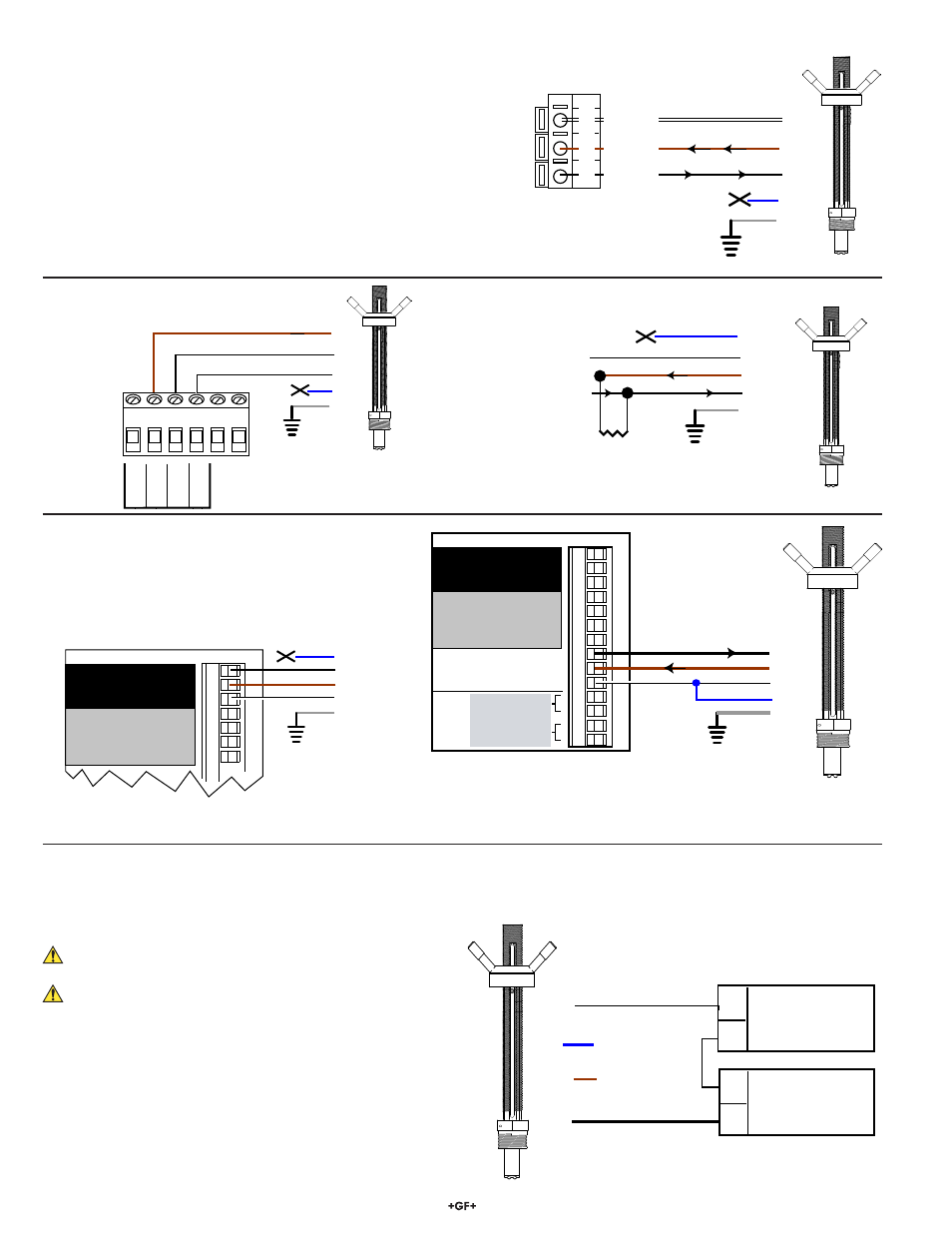
6.1 Wiring: Frequency output (Compatible with all POWERED Signet Flow instruments.)
6.2 Wiring: 8900 Multi-Parameter Controller
6. Wiring the 3-2552-XX-11 with Frequency or Digital (S
3
L) output
3-8900.621C
I/O Module 3-8900.401-X
1
2
3
4
5
6
7
8
9
10
11
12
13
14
+5VDC (Black)
Freq. Input (Red)
GND (Shield)
+5VDC (Black)
Freq. Input 2 (Red)
S L (Red)
GND (White/Shield)
+5VDC (Black)
S L (Red)
GND (White/Shield)
3
3
Analog Output 1
Analog Output 2
(if applicable)
(if applicable)
Frequency
Input
1
Frequency
Input 2
OR
S3L
Input
2
S3L
Input
1
+
-
+
-
White
Blue
Brown
Black
Shield
8900 S
L Wiring
3
3-8900.621C
I/O Module 3-8900.401-X
1
2
3
4
5
6
7
8
+5VDC (Black)
Freq. Input (Red)
GND (Shield)
+5VDC (Black)
Freq. Input 2 (Red)
S L (Red)
3
Frequency
Input
1
Frequency
Input 2
OR
S3L
Input
2
White
Blue
Brown
Black
8900 Frequency Wiring
Shield
•
The 2552 receives 5 VDC power from the 8900.
No additional power is required.
6.3 Wiring the 2552-XX-12 Magmeter with 4 to 20 mA Loop Output
The 2552 Magmeter is a traditional 2-wire passive 4 to 20 mA loop transmitter.
•
External loop power (21.6 to 26.4 VDC, 22.1 mA maximum)
is required. (See Power Requirements on pg. 1)
The maximum loop resistance the Magmeter can
accomodate is 300
Ω.
The cable length from the Magmeter to the loop monitor
cannot exceed 300 m (1000 ft).
•
All 2552 Magmeters are shipped from the factory with the 4
to 20 mA output scaled for 0 to 5 m/s (0 to 16.4 ft/s). If this
operating range is suitable, no adjustments are necessary.
The calibration charts in this manual list the 20 mA setpoint
for each pipe size. Use this information to program the 4 to
20 mA range of the loop device (PLC, Datalogger, recorder,
etc.).
2552 Magmeter
4 to 20 mA Loop
monitor
(Maximum 300 Ω)
+
+
-
-
24 VDC ± 10%
Brown
X
Blue
X
White
Loop - (Ground)
Black
Loop + (24 VDC)
NOTE:
The maximum cable length from the 2552 to the 8900 depends on the 8900
confi guration. Refer to the 8900 manual for complete information.
8550-1 Flow Transmitter
White
Blue
Brown
Black
9
8
7
Sensr IN
(RED)
Sensr V+
(BLACK)
Sensr Gnd
(SHIELD)
Shield
White
Blue
Brown
Black
Shield
Freq. IN
Sen. Pwr
.
Freq. IN
Iso. Gnd
Signet 5500
5-24 VDC
Sensor Ground
Frequency Out
10 KΩ
Install a pull-up resistor when
connecting the 2552 Magmeter
to other manufacturer's flowmeters.
White
Blue
Brown
Black
Non-Signet Instrument
Shield