General installation and grounding tips – GF Signet 2552 Metal Magmeter Flow Sensor User Manual
Page 4
4
2552 Magmeter
4. General Installation and Grounding Tips
4.1 Sensor
conditioning
The Magmeter output signal may be unstable immediately after installation. Allowing the sensor to soak in a full pipe (or in any
container of water) for 24 hours will stabilize the performance.
•
Very low conductivity fl uids may require a longer conditioning period.
•
The Magmeter may not operate properly in fl uids where the conductivity is less than 20
μS/cm.
4.2 Grounding
The 2552 Magmeter is unaffected by moderate levels of electrical noise, especially if installed in a properly grounded metal piping
system. However, in some applications it may be necessary to ground portions of the system to eliminate electrical interference. The
grounding requirements will vary with each installation.
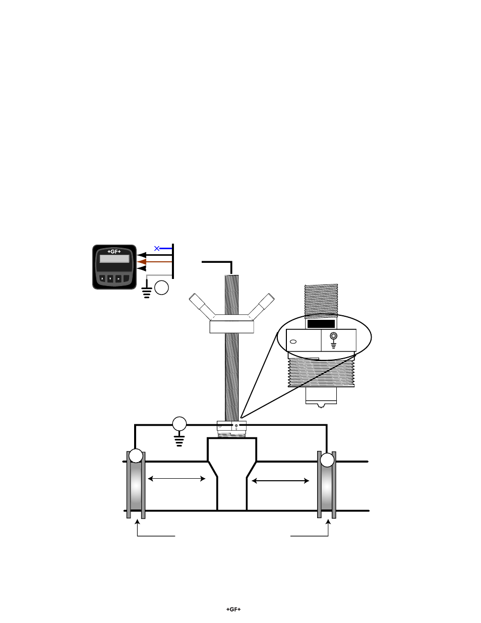
One or more of the following steps may be applied if the 2552 Magmeter is affected by electrical noise:
c
Connect a wire (14 AWG/2.08 mm
2
recommended) from the ground terminal screw on the sensor nut directly to a local Earth
ground.
d
Install fl uid grounding devices immediately upstream and downstream of the Magmeter.
Connect
the
fl uid grounds to the Earth ground terminal on the 2552.
Use
fl anged grounding rings or metal electrodes on plastic pipes, or metal clamps on metal pipes.
Fluid grounds must be in direct contact with the fl uid, and as near to the Magmeter as possible.
e
Connect the SHIELD conductor to Earth ground near the instrument.
Grounding rings on plastic pipe
(Installed between flanges)
(10 cm to 1.3 m)
(10 cm to 1.3 m)
4 in. to 50 in.
4 in. to 50 in.
FLOW →
→
Blue
Black
Brown
White
Shield
3.
Flow 6.25 GPM
Total 1234567.8>
ENTER
Signet Flow
Transmitter
1.
2.
2.
8550