Selecting a location – GF Signet 2552 Metal Magmeter Flow Sensor User Manual
Page 3
3
2552 Magmeter
3. Selecting a Location
The 2552 requires a fully developed turbulent fl ow profi le for accurate measurement. Selecting the correct location in the piping system
is critical to the performance of the magmeter.
Locate the magmeter where air bubbles will not contact the electrodes.
Placing the sensor in a vertical section of pipe, with fl ow going UPHILL is the fi rst choice for this requirement.
The piping system should be designed to keep the sensor wet at all times.
In applications where the conductivity of the process liquid is less than 100
μS, magmeters should be allowed to soak in a full pipe for
24 hours before operation.
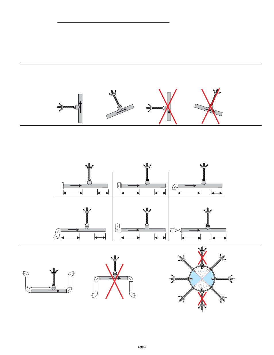
3.1 Vertical Installations Recommended
Locating the sensor where the fl ow is upward protects the sensor from exposure to air bubbles and may offset upstream turbulence
caused by pipe conditions and other hardware.
+GF+
15 x I.D.
5 x I.D.
Reducer
+GF+
10 x I.D.
5 x I.D.
Inlet
Outlet
Flange
+GF+
50 x I.D.
5 x I.D.
Valve/Pump
+GF+
40 x I.D.
5 x I.D.
2 x 90° Elbow
3 dimensions
25 x I.D.
5 x I.D.
2 x 90° Elbow
+GF+
20 x I.D.
5 x I.D.
90° Elbow
+GF+
+
GF
+
O.K.
+GF
+
O.K.
+GF+
O.K.
20 x ID
+GF+
+
GF
+
+GF
+
3.2 Horizontal
Installations
If the magmeter must be mounted in a horizontal section of pipe, take extra precautions to prevent air bubbles from passing over the
sensor.
Select a location with suffi cient distance of straight pipe immediately upstream of the sensor. The dimensions illustrated here are
intended for general guidance. Every piping system has unique characteristics, and requires individual evaluation.
Located the magmeter in a "trap" to prevent air bubbles and to
keep the electrodes wetted for best performance.
Air pockets and bubbles will travel at the top of a horizontal pipe,
so avoid vertical installations.
Sediments and debris that collect at the bottom of a horizontal
pipe will interference with the operation.