GF Signet 2552 Metal Magmeter Flow Sensor User Manual
Page 6
6
2552 Magmeter
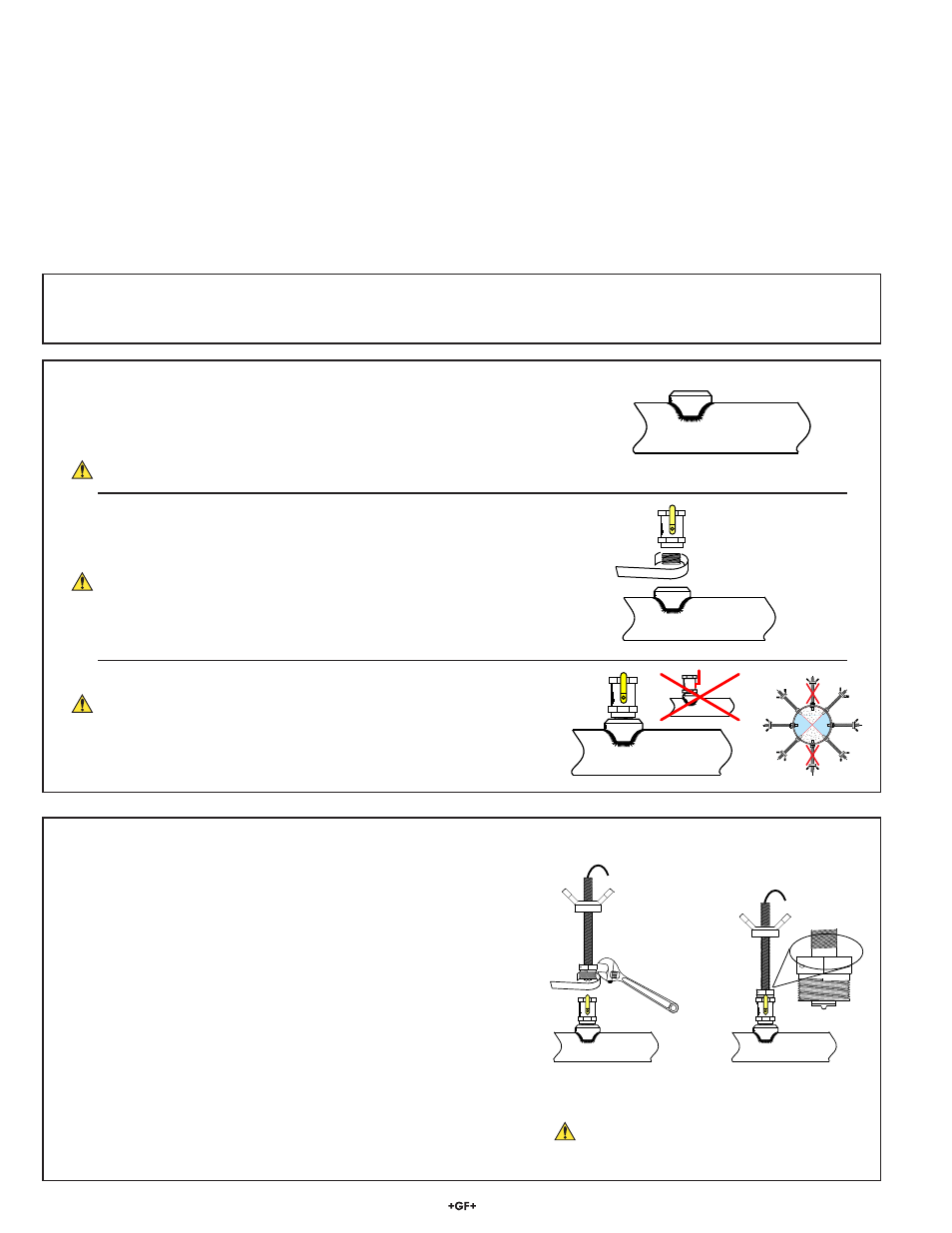
3. Install the Magmeter into the pipe
a. Apply sealing tape or paste to the male threads of the process
connector nut.
b. Tighten the process connector into the pipe.
• Do not damage the locking set screw when using tools.
• The sensor is marked to identify the downstream alignment.
The arrow MUST point DOWNSTREAM.
• Hold the outer sensor housing securely while threading the
process connector nut into the fi tting. This will prevent the cable
from becoming twisted around the sensor while the process
connector is tightened into the pipe.
c.
Loosen the set screw in the process connector nut.
d. Rotate the Acme threaded outer housing until the fl ow arrow is
aligned in the proper direction.
e. Secure the set screw suffi ciently to prevent the outer housing from
spinning.
Do not tighten the set screw yet. It may require additional
adjustment.
Not supplied with the 2552 Magmeter:
•
Female pipe fi tting (weld-on or saddle) with:
1¼ in. NPT or ISO 7/Rc 1¼ threads (2552-2)
1½ in. NPT or ISO 7/Rc 1½ threads (2552-3)
•
1¼ in. or 1½ in. ball valve (for hot tap installations)
•
32 mm (1¼ in.) or 40 mm (1½ in.) diameter drill
•
Pipe thread sealant suitable for application
• Pipe
wrench
• 32 mm (1¼ in.) pipe nipple
• 32 mm (1¼ in.) ball valve
• 32 mm (1¼ in.) drill bit
Supplied with 2552 Magmeter:
• Ruler
•
Brass alignment rod
•
H-dimension value for your pipe (See pages 6–9)
• Hex
wrench
•
2 clamp rings
• Grounding
screw
5. Magmeter
Installation
The following items are required to properly install the Magmeter:
1. Determine the H-dimension for the pipe.
•
The tables on pages 8–11 list the H-dimension metal pipe per ANSI 36.10 and ANSI 36.19.
•
Use the procedure on page 5 to determine the H-dimension for other types of pipe.
2. Prepare the pipe:
a.
Cut a 32 mm (1¼ in.) opening in the pipe.
b. Install a 1¼ in. (for 2552-1, 2552-2) or 1½ in. (for 2552-3) outlet onto the pipe.
This fi tting must withstand pressures up to 20 bar (300 psi).
•
For Hot-tap installations:
Thread a matching pipe nipple and ball valve into the outlet.
Use a suitable paste or sealing tape to provide a leakproof connection.
Hot- tap drilling requires special tools and skills.
This task should only be performed by qualifi ed personnel.
FLOW →
FLOW →
FLOW →
FLOW →
FLOW →
FLOW →
Position the ball valve handle so it is parallel to the pipe.
This will prevent the valve handle from interfering with
the adjustment and alignment of the magmeter.
•
Remember to tilt the magmeter to avoid air bubbles.
Wear gloves to grip the outer sensor housing.