Adjust the magmeter position and insertion depth, Secure the magmeter in position, Removal instructions for hot-tap installations – GF Signet 2552 Metal Magmeter Flow Sensor User Manual
Page 7
7
2552 Magmeter
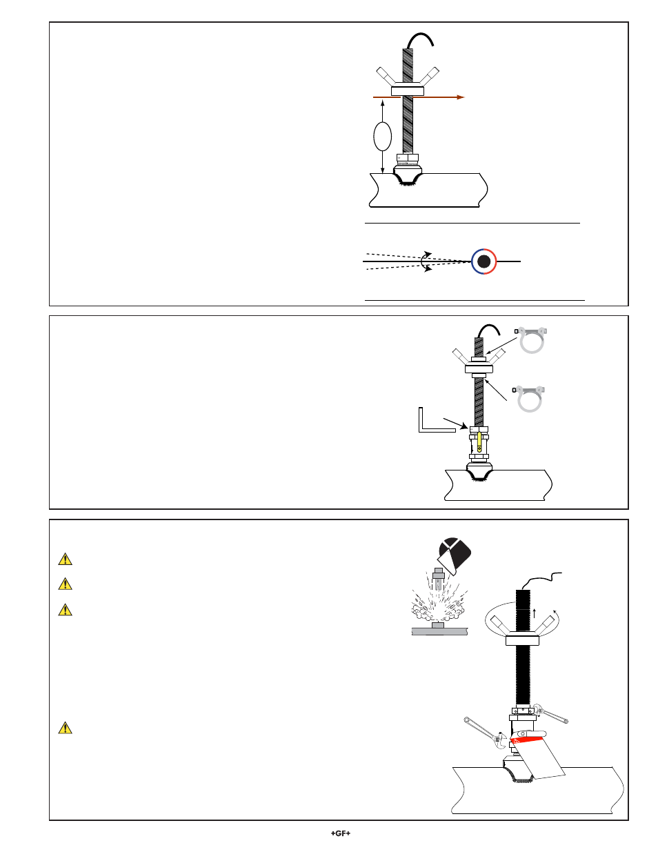
Pipe Top View
Align Magmeter with pipe ±1°
H
FLOW →
FLOW →
4. Adjust the magmeter position and insertion
depth
a. Insert the brass rod through the alignment reference hole
located directly below the sensor adjustment hub.
b. Adjust the height of the magmeter by turning the sensor
adjustment hub clockwise until the distance from the
OUTSIDE of the pipe to the bottom of the alignment rod is
equal to the H-dimension (as recorded on pg. 5).
•
Installation tip: If necessary, apply a suitable lubricant to
the Acme threads to facilitate smooth operation.
5. Secure the Magmeter in position
•
Secure the height adjustment by installing the two pipe clamps
above and below the sensor adjustment hub.
• Spread the clamp apart to wrap it around the outer
housing.
• Place one clamp immediately above and one clamp
immediately below the magmeter adjustment hub.
• Squeeze the clamp together until it is fi rmly locked around
the housing.
Set Screw
Set Screw
Wrench
FLOW →
The distance from the
OUTSIDE of the pipe
to the bottom of the
alignment rod must be
equal to the H-dimension
c.
Loosen the locking set screw and rotate the outer housing
to align the brass rod with the centerline if the pipe.
d. When the magmeter is adjusted for the proper height and
alignment, tighten the locking set screw fi rmly.
CAUTION: Overtightening the set screw may damage the
hex key.
6. Removal Instructions for Hot-tap Installations
REDUCE THE PROCESS TEMPERATURE TO LESS THAN 40 °C (104 °F)
REDUCE THE SYSTEM PRESSURE TO A SAFE LEVEL.
WEAR SUITABLE PROTECTIVE EQUIPMENT WHEN WORKING WITH
PRESSURIZED PIPES.
•
Remove the steel clamp from the top of the assembly.
•
Turn the sensor adjustment hub counter-clockwise until the sensor is fully
retracted. (The alignment sensor hole should be at the top of the outer housing slot.)
Apply a suitable lubricant to the ACME threads to ease the retraction.
•
Close the valve after raising the magmeter to the top of the housing.
Install a LOCKOUT TAG on the closed valve to prevent accidents!
• Remove the magmeter from the top of the valve.
• Loosen the locking set screw on the process connector nut.
• Use one pipe wrench to hold the valve in place while turning the process connector
nut with a second wrench.
• Do not damage the locking set screw when using tools.
UNDER PRESSURE!
HOLD VALVE IN PLACE!
Turn magmeter adapter ONLY!
CLOSE VALVE
BEFORE REMOVING MAGMETER!
DANGER!
DO NOT
DO NOT
OPEN
OPEN
THIS VAL
VE
THIS VAL
VE
This lock/tag ma
y
only be r
emoved b
y:
Name ___________
Dept. ____________
Expected dat
e for
completion:
_________