Sensor selection guide – GF Signet 2552 Metal Magmeter Flow Sensor User Manual
Page 13
13
2552 Magmeter
Sensor Selection Guide
The 2552 Magmeter can be installed into a variety of pipe sizes. Follow the steps below
to ensure that you choose the right sensor for your application.
Step 1: Determine how the sensor will be installed
• For retrofit installations, the ball valve
must be at least a 1¼ in. (or 1½ in.
for 2552-3) full port valve. The stack
height, or “A” dimension (see Fig. 2), is
the overall height from the top of the
pipe to the top of the ball valve, or the
top of the highest point of the stack
before the sensor is connected.
B. For Hot-Tap installations:
The stack height of the ball valve, nipple weldolet (threadolet) and pipe adapters should
be determined before the sensor is purchased.
• For new installations, Signet
recommends a 1¼ in. or 1½ in. full
port ball valve, a short nipple and
a weldolet (threadolet). The stack
height or “A” dimension (see Fig. 2) is
the overall height from the top of the
pipe to the top of the ball valve.
A. For standard (non Hot-Tap) installations:
The height of the weldolet (threadolet) and pipe adapter(s) should be determined before
the sensor is purchased.
• For retrofit installations, the stack
height, or “A” dimension (see Fig. 1), is
the overall height from the top of the
pipe to the highest point of the stack
before the sensor is connected.
• For new installations, Signet
recommends a weldolet (threadolet)
and an adapter to accommodate the
1¼ in. (or 1½ in. for 2552-3) sensor
process threads. The stack height,
or “A” dimension (see Fig. 1), is the
overall height from the top of the pipe
to the highest point of the stack.
Step 2: Determine how the sensor will be installed
Once the “A” dimension is determined, go to the sensor selection table and find your “A”
dimension on the left column. Next, find the appropriate pipe size at the top of the chart.
To determine the correct sensor size locate where the pipe size column meets the max
“A” dimension row.
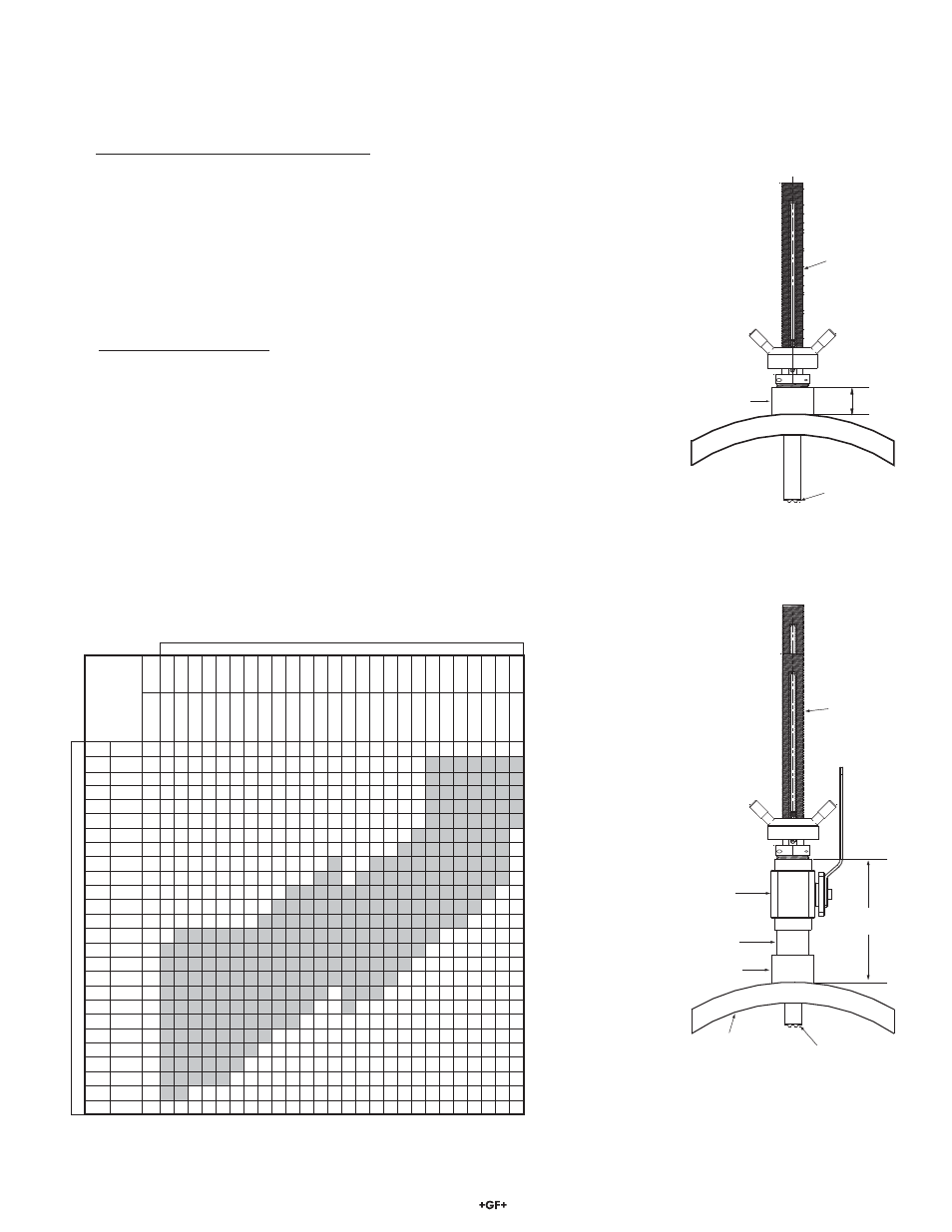
“A”
Dimension
Weldolet
or Saddle
Sensor
Housing
Sensor
Fig. 1
Standard installation with “A”
dimension using a weldolet
(threadolet)
“A”
Dimension
Weldolet
Nipple
Ball
Valve
Pipe
Wall
Sensor
Housing
Sensor
Fig. 2
Hot-Tap installation with “A”
dimension using a ball valve,
short nipple and weldolet
(threadolet)
Step 3: Refer to Ordering Information to select corresponding part numbers
Legend:
2: Use 3-2552-2,
max. insertion =
236 mm (9.3 in.)
3: Use 3-2552-3
max. insertion =
368 mm (14.8 in)
in
ches
2
2.
5
3 to 31/
2"
4
5
6 to 8"
10
12 to 14"
16
18
20
22
24
26 to 28"
30 to 32"
34
36 to 38"
40 to 42"
48
54
60
66
72
78
84
102
DN
50
65
80 to 90
100
125
150 to 200
250
300 to 350
400
450
500
550
600
650 to 700
750 to 800
850
900 to 950
1000 to 1100
1200
1400
1500
1700
1800
2000
2100
2550
mm
inches
50.8
2
2
2
2
2
2
2
2
2
2
2
2
2
2
2
2
2
2
2
2
3
3
3
3
3
3
3
63.5
2.5
2
2
2
2
2
2
2
2
2
2
2
2
2
2
2
2
2
2
2
3
3
3
3
3
3
3
76.2
3
2
2
2
2
2
2
2
2
2
2
2
2
2
2
2
2
2
2
2
3
3
3
3
3
3
3
88.9
3.5
2
2
2
2
2
2
2
2
2
2
2
2
2
2
2
2
2
2
2
3
3
3
3
3
3
3
101.6
4
2
2
2
2
2
2
2
2
2
2
2
2
2
2
2
2
2
2
2
3
3
3
3
3
3
3
114.3
4.5
2
2
2
2
2
2
2
2
2
2
2
2
2
2
2
2
2
2
3
3
3
3
3
3
3
127
5
2
2
2
2
2
2
2
2
2
2
2
2
2
2
2
2
2
3
3
3
3
3
3
3
3
139.7
5.5
2
2
2
2
2
2
2
2
2
2
2
2
3
2
2
3
3
3
3
3
3
3
3
3
3
152.4
6
2
2
2
2
2
2
2
2
2
2
2
3
3
2
3
3
3
3
3
3
3
3
3
3
3
165.1
6.5
2
2
2
2
2
2
2
2
2
3
3
3
3
3
3
3
3
3
3
3
3
3
3
3
177.8
7
2
2
2
2
2
2
2
3
3
3
3
3
3
3
3
3
3
3
3
3
3
3
3
190.5
7.5
2
2
2
2
2
2
2
3
3
3
3
3
3
3
3
3
3
3
3
3
3
3
228.6
9
2
3
3
3
3
3
3
3
3
3
3
3
3
3
3
3
3
3
3
3
241.3
9.5
3
3
3
3
3
3
3
3
3
3
3
3
3
3
3
3
3
3
3
254
10
3
3
3
3
3
3
3
3
3
3
3
3
3
3
3
3
3
3
266.7
10.5
3
3
3
3
3
3
3
3
3
3
3
3
3
3
3
3
3
279.4
11
3
3
3
3
3
3
3
3
3
3
3
3
3
3
3
292.1
11.5
3
3
3
3
3
3
3
3
3
3
3
3
304.8
12
3
3
3
3
3
3
3
3
3
3
317.5
12.5
3
3
3
3
3
3
3
3
330.2
13
3
3
3
3
3
3
3
342.9
13.5
3
3
3
3
3
3
355.6
14
3
3
3
3
3
375.9
14.8
3
3
381
15
Pipe Size
Ma
x
. "A
" D
im
This chart is based on the thickest commonly available pipe.