Electrical connection with cable gland – Burkert Type 8791 User Manual
Page 30
30
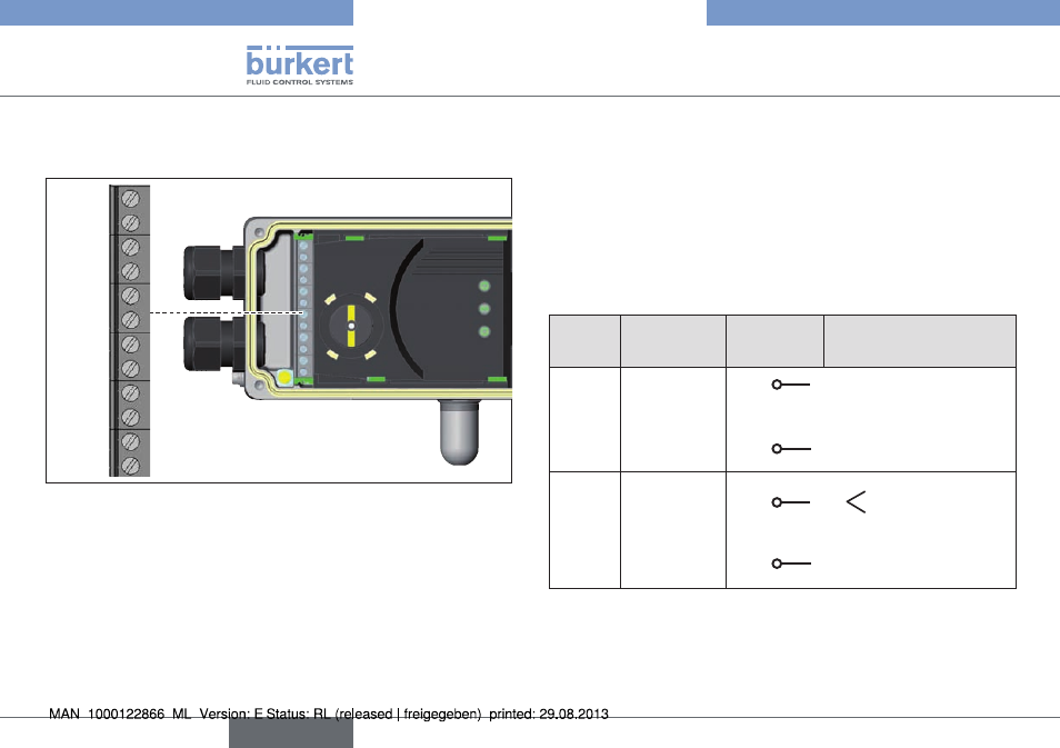
Electrical connection
10.4. electrical connection with cable
gland
11 +
12 –
81
82
31 +
32 –
A
B
+
–
+24 V
GND
remote
sensor
Fig. 21: Designation of the screw-type terminals
10.4.1. connection of the terminals
→
Unscrew the 4 screws on the housing cover and remove the
cover.
The screw-type terminals are now accessible.
→
Connect terminals according to the configuration.
10.4.2. Terminal assignment for input signals
from the control centre (e.g. plc)
terminal configuration on the
device side
external circuit / signal
level
11 +
Set-point
value +
11 +
+ (0/4 – 20 mA)
not galvanically isolated
12 –
Set-point
value GND
12 –
GND set-point value
81 +
Binary input + 81 +
+
0 – 5 V (log. 0)
10 – 30 V (log. 1)
82 –
Binary input – 82 –
GND (identical with the
GND supply voltage)
Tab. 15: Terminal assignment; input signals of the control centre
english
Type 8791
- Type 1062 (112 pages)
- Type 8750 (82 pages)
- Type 1050 (4 pages)
- Type 8750 (64 pages)
- Type 8681 (40 pages)
- Type 8681 (90 pages)
- Type 8798 (106 pages)
- Type 8798 (2 pages)
- Type 8791 (4 pages)
- Type 8792 (252 pages)
- Type 8718 (34 pages)
- Type 8792 (118 pages)
- Type 8791 (15 pages)
- Type 8792 (136 pages)
- Type 8791 (184 pages)
- Type 8791 (28 pages)
- Type 8791 (21 pages)
- Type 8791 (154 pages)
- Type 0911 (76 pages)
- Type 0911 (46 pages)
- Type 0911 (64 pages)
- Type 0911 (84 pages)
- Type 1058 (31 pages)
- Type 1060 (4 pages)
- Type 1066 (112 pages)
- Type 1067 (158 pages)
- Type 1077-2 (33 pages)
- Type 1094 (12 pages)
- Type 1094 (41 pages)
- Type 1094 (82 pages)
- Type 1094 (126 pages)
- Type 1115 (25 pages)
- Type 1150 (99 pages)
- Type 1541 (2 pages)
- Type 5142 (6 pages)
- Type 8619 (40 pages)
- Type 8619 (134 pages)
- Type 8620 (177 pages)
- Type 8622 (4 pages)
- Type 8623 (130 pages)
- Type 8623 (90 pages)
- Type 8625 (118 pages)
- Type 8624 (124 pages)
- Type 8718 (254 pages)