Burkert Type 8791 User Manual
Page 29
29
Electrical connection
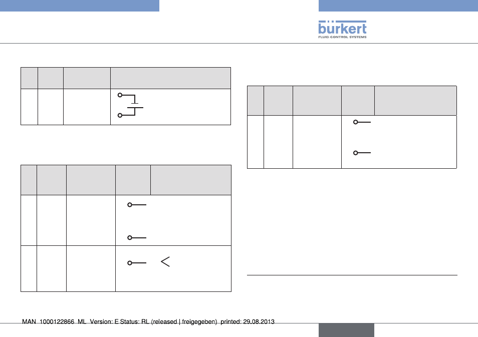
10.3.2. pin assignment for operating voltage
pin Wire
color
7)
configuration external circuit / signal level
3
green GND
3
4
24 V DC ± 10 %
max. residual ripple 10%
4
yellow +24 V
Tab. 12: Pin assignment; operating voltage
10.3.3. pin assignment for input signals from
the control centre (e.g. plc)
pin Wire
color
7)
configuration on the
device
side
external circuit /
signal level
1
white
Set-point
value +
(0/4 – 20 mA)
1
+ (0/4 – 20 mA)
not galvanically isolated
2
brown
Set-point
value GND
2
GND set-point value
5
grey
Binary input
5
+
0 – 5 V (log. 0)
10 – 30 V (log. 1)
with reference to
Pin 3 (GND)
Tab. 13: Pin assignment; input signals of the control centre
10.3.4. pin assignment for output signals to
the control centre (e.g. plc) - required
for analogue output option only
pin Wire
color
7)
configuration on the
device
side
external circuit / signal
level
8
red
Analogue
feedback +
8
+ (0/4 – 20 mA)
not galvanically isolated
7
blue
Analogue
feedback GND
7
GND (identical with the
GND supply voltage)
Tab. 14: Pin assignment; output signals to the control centre
7)
The indicated wire colors refer to the connection cable, part no.
919061, available as an accessory
english
Type 8791