Burkert Type 3236 User Manual
Page 38
38
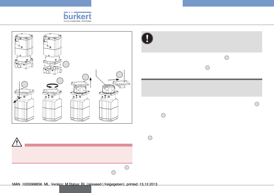
Repairs
Type 2035 / 3236
Guide bolt
1
45°
Diaphragm
Pressure
pieces
2
3
4
5
Fig. 32: Disassembly of the RV110 pneumatic actuator
assembly of actuator and diaphragm
Caution!
danger of injury due to movable parts in the actuator.
▶ When applying or removing the pilot pressure on the actuator
keep members and other objects away from the actuator openings.
→
Insert the diaphragm into the T-guide of the pressure pieces
6
.
Make sure that the four spacing sleeves are installed
7
.
For easier assembly of the pressure pieces the actuator
spindles should be in the lower position (
Close) (CFA, NC:
by removing the pilot pressure; CFB, NO: by applying the
pilot pressure).
→
Insert the pressure pieces into the actuator
8
. Make sure that
the actuator spindles are fully inserted into the corresponding
recesses of the pressure pieces
9
.
note!
damage to diaphragm and valve malfunction.
▶ Turn the diaphragm and pressure pieces only far enough to align
the screw holes of the actuator and the diaphragm.
→
Turn the diaphragm and pressure piece no more than 45° until
the holes of the diaphragm line up with those of the actuator
10
.
→
Screw in the guide bolt and tighten with a torque of approx.
10 Nm
11
.
→
Move the actuator to the upper actuator position (CFA, NC: by
applying pilot pressure; CFB, NO: by removing the pilot pressure).
→
Put the actuator / diaphragm on the body with correct alignment
12
(so that the markings made previously align).
→
Tighten the diagonally opposed body screws / nuts until there
is visible, uniform mechanical contact between the valve body,
diaphragm and actuator.
→
Tighten the diagonally opposed body screws / nuts twice with a
quarter turn and using the same torque in each case.
english