Burkert Type 3236 User Manual
Page 26
26
Assembly
Type 2035 / 3236
In aggressive surroundings and in situations where moisture
could enter the actuator via the exhaust air port or muffler
the exhaust air should be collected and ducted to a non-
critical location.
procedure:
→
Remove the yellow protective stopper.
→
Connect the pilot medium to the pilot air port with the aid of the
installation and dimensional drawing supplied.
Control function B:
The pilot pressure should be selected to be as low as pos-
sible to reduce wear on the diaphragm.
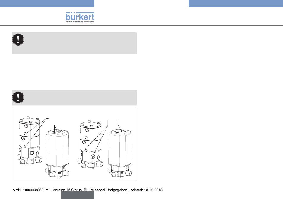
Pilot air
ports
Connections for
proximity sensors
Fig. 24: Pneumatic connection; installation of a proximity switch
8.5.
installation of the inductive
proximity switch
The switch is installed using the M8 x 1 or M12 x 1 thread on the
side of the actuator (for RV50 with PP cover on the upper side).
→
Connect with the aid of the installation and dimensional drawing
supplied.
→
Remove the yellow protective stopper.
→
Move the actuator to the position that is to be queried by the
proximity switch:
rV50/70:
lower proximity switch: Move the actuator to the lower actuator
position (CFA, NC: by removing pilot pressure; CFB, NO: by
applying the pilot pressure).
upper proximity switch: Move the actuator to the upper actuator
position (CFA, NC: by applying pilot pressure; CFB, NO: by
removing the pilot pressure).
rV110:
Move the actuator to the lower actuator position (CFA, NC:
by removing pilot pressure; CFB, NO: by applying the pilot
pressure).
→
Screw in the proximity switches until they connect with the pressure
pieces.
→
Then unscrew the proximity switches by one half to one turn.
→
Secure the proximity switches with the aid of securing nuts (the
second nut and the two washers supplied are not needed).
→
Test the functionality of the proximity switches.
english