0 overview, 4 idh4 series start-up and reboot routine – Alpha Technologies AlphaNet IDH4 for XM2 and XM2-300HP Series - Technical Manual User Manual
Page 12
12
746-257-B2-001, Rev. B (01/2014)
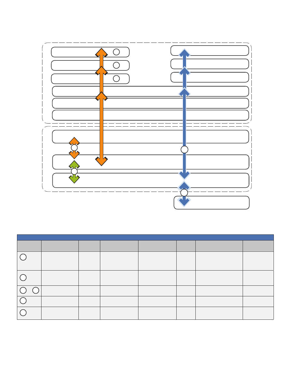
The above diagram, read left to right, indicates the order of operations as the transponder comes online.
There are certain conditions that must exist for each step to occur, resulting in successful data monitoring and
management. The numbers below correspond to the numbered arrows above.
Network Management System
MIB Browser
Web Browser
IDH4 Series
Power Supply
CMTS
Firewalls
Local Laptop
TCP/IP
Network
HFC Network
4
5
Switches
Routers
7
6
1
2
3
TFTP Server
TOD Server
DHCP Server
2.0 Overview
2.4
IDH4 Series Start-up and Reboot Routine
Refer to Ref #6 in the above table for normal LED behavior when the IDH4 is fully functional.
•
Blue Rx/Tx Power LED indicates Rx/Tx Power at a warning level. Make the necessary RF level adjustments.
•
Red Rx/Tx Power LED indicates Rx/Tx Power at an alert level. Make the necessary RF level adjustments.
Table 2-1, LEDs and Indications
LEDs and Indications
Ref #
Communications
State
ALM/RDY
Downstream (DS)
Registration (REG)
Rx/Tx
Power
Communications (COM) Ethernet (ETH)
Transponder Initializing/
Searching for
Downstream DOCSIS
channel
ON (Green)
Flashing
OFF
OFF
OFF
OFF
DOCSIS Channel locked
- Completing upstream
and network registration
ON (Green)
ON
Flashing
ON (Green)
OFF
OFF
to
Online - Registration
Complete
Flashing
(Green)
ON
ON
ON (Green)
OFF and ON
OFF
IDH4 Series fully
functional
Flashing
(Green)
ON
ON
ON (Green)
Bursts when communicating to
multiple power supplies (IDH4X
OFF
Laptop Connected to
local Ethernet port
Flashing
(Green)
ON
ON
ON (Green)
Bursts
LNK - ON
ACT - Bursts
6
1
2
3
5
7