2 reassembly procedure – Alpha Technologies AlphaGen 3.5_5.0kW Kohler COM5 User Manual
Page 65
TP-6482 8/06
65
Section 7 Disassembly/Reassembly
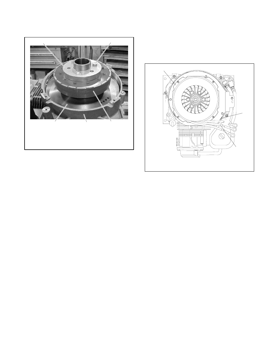
d. Remove the three screws securing the spacer
and rotor to the flywheel. Remove the spacer
and the rotor. See Figure 7-5.
TP-6092
1
3
5
2
1. Spacer
2. Rotor/spacer screws (3)
3. Rotor
4. Engine adaptor
5. Flywheel
4
Figure 7-5
Rotor and Spacer (shroud and stator
removed)
5. Remove the flywheel, if necessary.
a. Remove the thrubolt and convex washer at the
center of the flywheel taper. See Figure 7-4.
b. Pull the flywheel off the engine crankshaft.
7.2 Reassembly Procedure
1. Install the flywheel, if it was removed.
a. Clean the engine crankshaft and flywheel taper
with a dry cloth.
b. Slide the flywheel onto the engine crankshaft.
c. Install the M10-1.50 x 45 mm (1.772 in.)
thrubolt and convex washer. Install the washer
with the convex side up, as shown in
Figure 7-4.
d. Use a torque wrench to tighten the thrubolt to
67 Nm (49.4 ft. lb.).
2. Reassemble the alternator. See Figure 7-4.
a. Slide the rotor over the flywheel taper, aligning
the bolt holes in the rotor and the flywheel.
b. Place the spacer on the rotor, aligning the bolt
holes.
c. Use three 63.5 mm (3/8-16 x 2.5 in.) hex head
screws to secure the spacer and rotor to the
flywheel. See Figure 7-5. Do not tighten the
screws.
d. Place the stator in position as shown in
Figure 7-6. Feed the stator leads through the
opening in the alternator scroll.
1
1. Stator
2. Scroll
3. Stator leads
M-337000A-H
3
2
Figure 7-6
Generator Set Top View
e. Use four 44.5 mm (1/4-20 x 1.75 in. ) socket
head cap screws to secure the stator to the
alternator adaptor. Do not tighten the screws.
f. Use a 0.25 mm (0.010 in.) feeler gauge to
check the gap between the rotor and stator at
several places. Adjust the stator position so
that the gap is even all around. Use a torque
wrench
to
tighten
the
rotor
screws
to
38 Nm (28.0 ft. lb.). Tighten the stator screws
to 11 Nm (8.1 ft. lb.) and verify that the gap is
0.25 mm (0.010 in.) all around.
3. Install the fan.
a. Place the fan on the spacer, aligning the bolt
holes with the three unused holes in the spacer,
rotor, and flywheel.
b. Use three 82.5 mm (3/8-16 x 3.25 in.) hex head
screws and washers to secure the fan. Use a
torque wrench to tighten the screws to
25 Nm (18.4 ft. lb.).
4. Connect the stator leads to the voltage rectifier.
Tighten the voltage rectifier terminal screws to
5 Nm (44 in. lb.).