6 voltage programming shunt, 7 control board replacement, 4 ignition circuits – Alpha Technologies AlphaGen 3.5_5.0kW Kohler COM5 User Manual
Page 60: Figure 6-6 programming shunt location, Figure 6-7 jumper configurations, Notice, Check that all plug connections are secure, Power selection jumpers kw rating jp1a jp1b
TP-6482 8/06
60
Section 6 Controller Operation and Test
6.5.4
Ignition Circuits
Move the generator set master switch to the START
position. If the engine cranks but does not start, check
for voltage from lead 70 to ground at terminal B on the
ignition module and at the positive terminal of the
ignition coil. If no voltage is present during cranking,
replace the controller circuit board. If the ignition system
is receiving 12 VDC, check the spark plug and test the
other ignition system components.
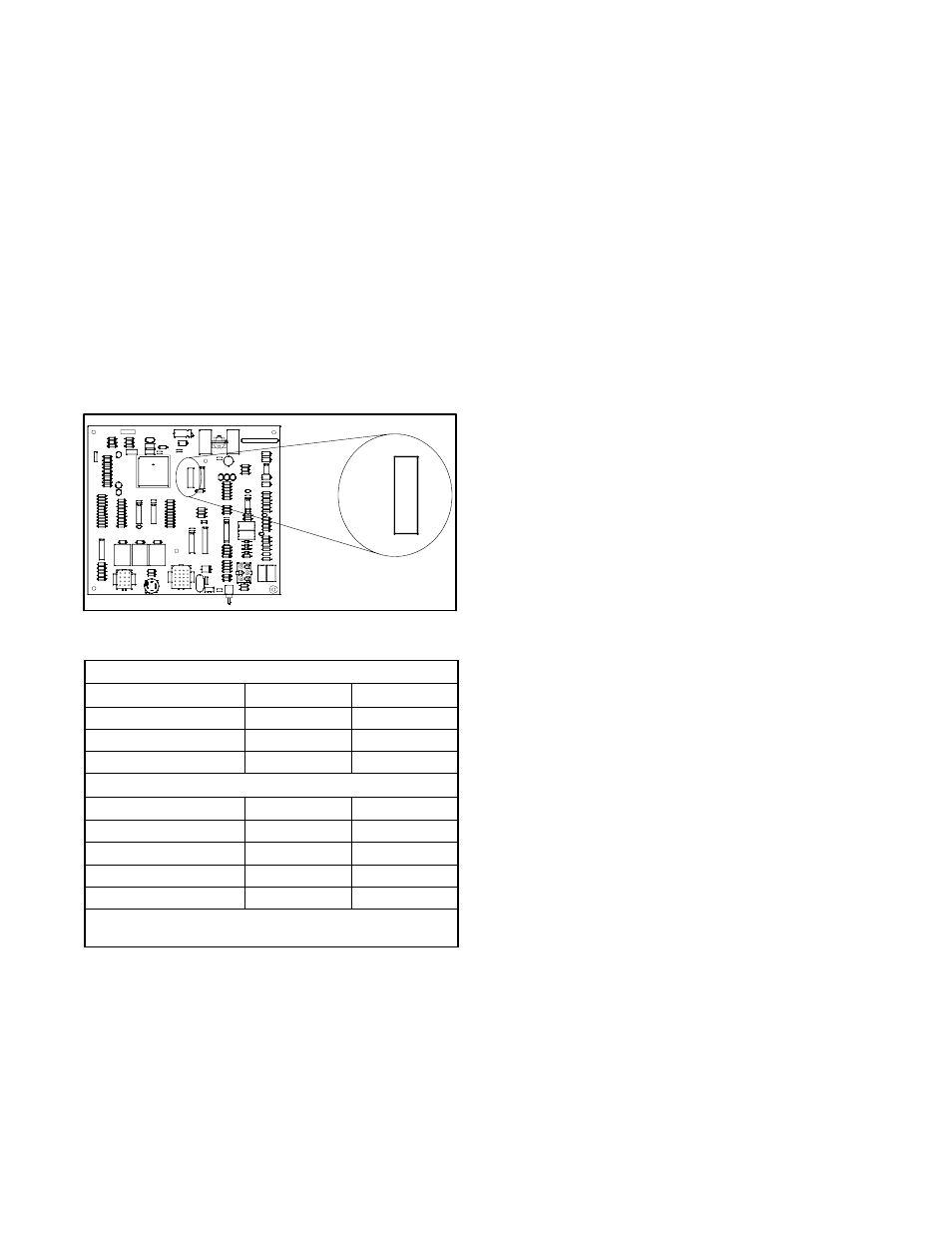
6.6 Voltage Programming Shunt
Control board GM22402 uses a programming shunt for
voltage selection. See Figure 6-6 for the programming
shunt location. Set programming shunts JP1A through
JP1D to select the generator set kW and voltage as
shown in Figure 6-6 and Figure 6-7.
GM22402
3.5 5.0 7.5
R51
R52
D26
D27
D28
R53
SW1
D29
R43
MC1413BP
D7
D9
D8
D5
D6
17
P1
1 3
K110 12
D20
F1
D21
TYPE
12.5A
250V
FST1
K2
K3
P2
4
V1
20
R48
C24
R32
C19D23
D24 4
D22R45
R46
R47
Z1
R44
6
R3
R13
U1
R14
R15
R17
R16
D4
D3
C1
R11
R12
R10
R9
R8
R100
R7
R6
R5
R4
P4R2
+
D17
C4
C5
D16
D15
+
C3
D14
D13
+
+ U4
D18
C9
D19
74HC14 U574HC14
U3
LED1
D12
D11
Q1
FAIL
GEN
R
C12
C8
87C196KB16
C18
U7
L293D
U8
R25
R28
R26
R27
R23
R24
R22
C16
C17
R30
R31
C23
L297/1
R42
LM2902N
C29
+
U9
R39
R40
R41
C28
JP1G
8
R21
R20
JP1H
R29
9
JP1B
JP1D
JP1E
JP1F
JP1C
1
JP1A
JP1
16
U6
R33
R37
R38
R36
R35
R34
C21
Q2 R50
Q3Q4
D25
R49
D1
U2
R1
D2
C2
R18
C7
C6
R19
D10
C11
1
+
C10
Y1
C14
+
C15
C13
VR1
C20 +
R63
C37
R54
R55
1
R64
R65
P3
3 C36
+
LM2903N
C35
R62
D33
Z3
Z2
R61
D32
D31
D30
R60
C27 C34
C33
R56
R59
R58
R57
C26
U10
C25
+
C32 +
U11MAX680
C31
C30
BARCODE
+
JP1G
8
JP1H
9
JP1B
JP1D
JP1E
JP1F
JP1C
1
JP1A
JP1
16
Figure 6-6
Programming Shunt Location
Power Selection Jumpers
kW rating
JP1A
JP1B
3.5
OUT
OUT
5.0
OUT
IN
7.5
IN
OUT
Voltage Selection Jumpers
Voltage Rating, VDC
JP1C
JP1D
24
OUT
OUT
36
OUT
IN
48
IN
OUT
96
IN
IN
Note: Jumpers JP1E and JP1F have no function.
Jumpers JP1G and JP1H are for factory use only.
Figure 6-7
Jumper Configurations
6.7 Control Board Replacement
NOTICE
Electrostatic discharge damage. Electrostatic discharge
(ESD)
damages
electronic
circuit
boards.
Prevent
electrostatic discharge damage by wearing an approved
grounding wrist strap when handling electronic circuit boards
or integrated circuits. An approved grounding wrist strap
provides a high resistance (about 1 megohm), not a direct
short, to ground.
If the controller tests in Section 6 or the troubleshooting
procedures in Section 4 indicate that the control board
needs to be replaced, follow these guidelines:
D
Keep the new board in its protective wrapping until
installation.
D
Wear a grounding strap while handling the circuit
board to prevent damage to the circuit board
components.
D
Set the programming shunts for kW and voltage. See
Section 6.6.
D
Check that all plug connections are secure.
D
Calibrate the voltage after installing the board.
The new circuit board must be calibrated after
installation. Use the following procedure to calibrate the
board.
Installation Procedure
1. Place the generator set master switch in the OFF
position.
2. Disconnect the power to the battery charger, if
equipped.
3. Disconnect the generator set engine starting
battery(ies), negative (--) lead first.
4. Open the enclosure to access the control board.
5. Disconnect all connectors to the control board, and
remove the board from the enclosure.
6. Before
installing
replacement
control
board
GM22402, install the jumper(s) (294634) as shown
in Figure 6-7 to obtain the rated power (kW) and
voltage for the generator set. Zero (0) to three
jumpers are required, depending on the selected
voltage and power ratings. See Figure 6-6 for the
jumper locations.
Note: Verify that connector P2 is not connected to
the board during jumper installation or
removal.