3 controller operation, 1 control connections – Alpha Technologies AlphaGen 3.5_5.0kW Kohler COM5 User Manual
Page 16
TP-6482 8/06
16
Section 2 Operation
2.3 Controller Operation
Microprocessor-based
controls
provide
complete
control of the engine and generator. The control system
accepts remote control inputs for generator start and run
and delivers local and remote annunciation of unit
status. Internal functions of the controls include start
and stop logic, fault monitoring, generator voltage and
engine speed governing, and fault annunciation through
local LEDs.
A three-position generator set master switch on the
control board allows local or remote control of the
generator set. The RUN and STOP positions provide
local control of the generator set. The STOP position
also resets controller faults. The AUTO position allows a
remote device to start and stop the generator set. See
Section
2.3.2
for
remote
start/stop
connection
information.
Note: Set the generator set master switch to the AUTO
position to allow remote control of generator set.
M-337000C-B
1
2
1. Generator set master switch
2. Common fault indicator LED
FAULT
RUN
AUTO
STOP
Figure 2-1
Generator Set Controls
1. Generator set master switch
1
TP6076
Figure 2-2
Generator Set Master Switch Location
2.3.1
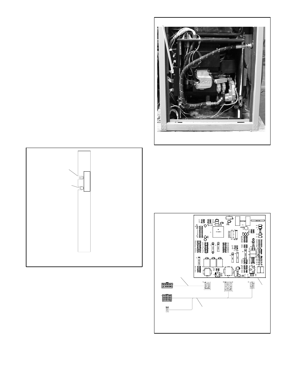
Control Connections
Wiring harnesses connect the generator set control
board to the remote controls and the engine. Figure 2-3
shows the wiring harness connections to the control
board. Refer to the wiring diagrams in Section 8 for
connector pin identification.
Figure 2-5 defines the
abbreviations used for the pin diagrams.
GM14140-AL
1. Cabinet interface harness
2. Generator set control circuit board
3. Engine interface harness
1
3
2
Figure 2-3
Generator Set Control Connections