8 ignition system, 9 cooling system – Alpha Technologies AlphaGen 3.5_5.0kW Kohler COM5 User Manual
Page 29
TP-6482 8/06
29
Section 3 Scheduled Maintenance
Refer to the cabinet manufacturer’s operation and
maintenance
manual
for
battery
maintenance
instructions.
3.8 Ignition System
3.8.1
Ignition System Description
The generator set uses a battery-powered coil ignition
system.
Ignition system components include the
ignition module, ignition coil, wiring, and spark plug. See
the service views in Section 1.4 for ignition system
component locations.
Maintain the spark plug using the instructions in Section
3.8.2. The other ignition system components do not
require routine maintenance.
3.8.2
Spark Plug
Reset the spark plug gap or replace the plug with a new
plug if necessary. Replace the plug at the intervals
shown in the service schedule in Figure 3-1.
1. Clean the area around the base of the spark plug to
keep dirt and debris out of the engine.
2. Remove the spark plug and check its condition.
Verify that the insulator is a light tan or gray color.
Replace the spark plug if the insulator is
discolored, the plug is coated with deposits, or the
electrodes are pitted or worn.
3. Check the spark plug gap using a wire feeler
gauge. Adjust the gap to 0.76 mm (0.030 in.) by
carefully bending the ground electrode.
See
Figure 3-9 and Figure 3-10.
1--514
Figure 3-9
Checking the Spark Plug Gap
1--511
Figure 3-10 Adjusting the Spark Plug Gap
3.9 Cooling System
The air inlet and outlet vents are located near the top of
the cabinet. To prevent generator set damage caused
by overheating, keep the housing cooling inlets and
outlets clean and unobstructed at all times.
Note: Do not block the generator set cooling air inlet or
mount other equipment above it. Overheating
and severe generator damage may occur.
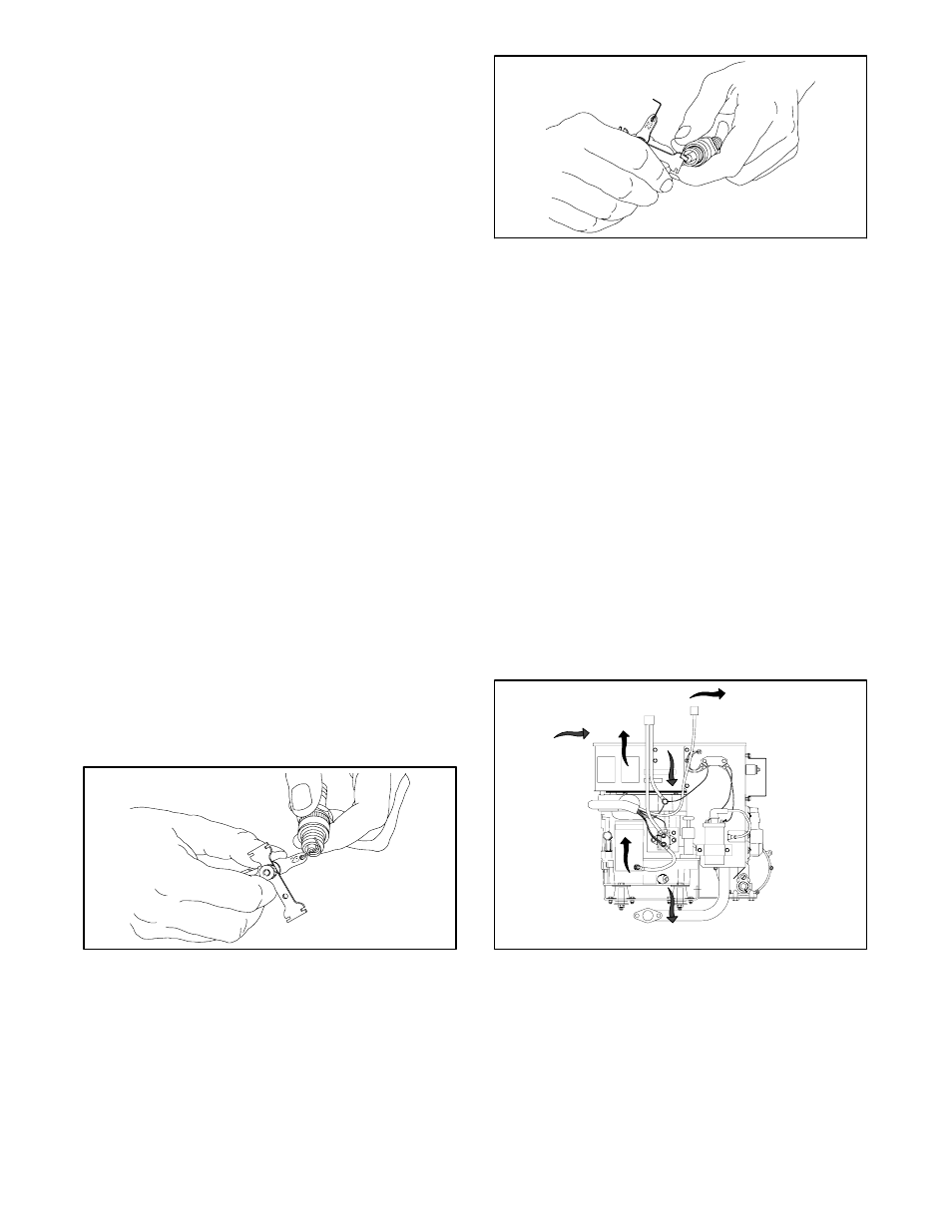
Figure 3-11 shows the flow of air through and around the
generator set. Ducts inside the cabinet, which are not
shown in this figure, direct the flow of cooling air. The
generator fan draws cooling air through the opening in
the back of the cabinet. The air flows into the alternator
at the top of the unit and down over the engine. The air
then flows up over the exhaust piping and muffler, mixes
with the engine exhaust, and discharges at the cabinet
outlet in the front of the cabinet.
M337000B-B
Figure 3-11 Cooling Air Flow