8 alternator, 1 stator – Alpha Technologies AlphaGen 3.5_5.0kW Kohler COM5 User Manual
Page 52
TP-6482 8/06
52
Section 5 Component Testing and Adjustment
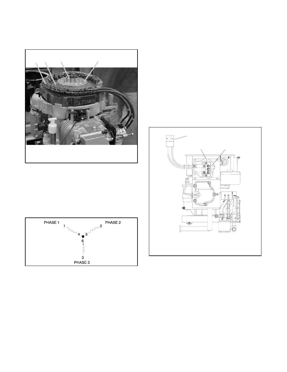
5.8 Alternator
The alternator is connected directly to the engine. The
alternator uses a permanent magnet rotor and a 3-lead
3-phase stator. See Figure 5-25.
TP--6092
1
1. Stator
2. Rotor
3. Flywheel taper
4. Spacer
2
4
3
Figure 5-25 Alternator (shroud and fan removed to
show components)
5.8.1
Stator
The stator contains coils of wire laid in a laminated steel
frame. The three stator leads are connected together in
a wye configuration. See Figure 5-26.
GM11539
Figure 5-26 Stator Windings
The stator leads supply voltage to the voltage rectifier
and the speed-sensing circuit. Before testing, inspect
the stator for heat discoloration, visible damage to
housing lead wires, exposed coil windings, or exposed
areas of frame laminations. Use an ohmmeter to check
the continuity of the stator windings using the following
procedure.
Stator Test Procedure
1. Disconnect the power to the battery charger, if
equipped.
2. Disconnect the generator set engine starting
battery, negative (--) lead first.
3. Disconnect output connector P8 from the load.
See Figure 5-27.
4. Disconnect the stator leads from the voltage
rectifier. See Figure 5-27.
Note: Disconnect all stator leads from the voltage
rectifier before performing the test.
5. Set the ohmmeter on R x 1 scale. Touch the red
meter lead to the black lead and adjust the
ohmmeter to show zero ohms.
3
M-337000B
1. Output connector P8
2. Voltage rectifier
3. Stator leads (AC Side)
2
1
Figure 5-27 Stator Lead Connections to Rectifier