1 disassembly procedure – Alpha Technologies AlphaGen 3.5_5.0kW Kohler COM5 User Manual
Page 63
TP-6482 8/06
63
Section 7 Disassembly/Reassembly
Section 7 Disassembly/Reassembly
Before disassembly, remove the generator set from any
enclosure.
Refer to Section 3.3 for instructions.
Disconnect the battery (negative [--] lead first), fuel line,
exhaust system, remote start switch, load leads, and
other wiring harnesses. In addition to the precautions
included in the text, observe all safety precautions listed
at
the
beginning
of
this
manual
during
the
disassembly/reassembly procedure.
Hazardous voltage.
Can cause severe injury or death.
Only authorized personnel should
open the enclosure.
(600 volts and under)
WARNING
Accidental starting.
Can cause severe injury or death.
Disconnect the battery cables before
working
on
the
generator
set.
Remove the negative (--) lead first
when
disconnecting
the
battery.
Reconnect the negative (--) lead last
when reconnecting the battery.
WARNING
Disabling the generator set.
Accidental starting can
cause severe injury or death.
Before working on the
generator set or equipment connected to the set, disable the
generator set as follows: (1) Place the generator set start/stop
switch in the STOP position. (2) Disconnect the power to the
battery charger, if equipped. (3) Remove the battery cables,
negative (--) lead first. Reconnect the negative (--) lead last
when reconnecting the battery. Follow these precautions to
prevent the starting of the generator set by the remote
start/stop switch.
NOTICE
Hardware damage. The engine and generator set may use
both American Standard and metric hardware. Use the correct
size tools to prevent rounding of the bolt heads and nuts.
7.1 Disassembly Procedure
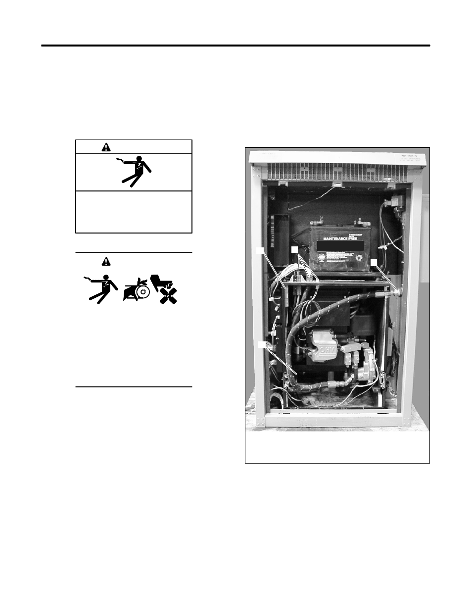
1. Follow the instructions in Section 3.3 to open the
cabinet, disconnect the generator set, and remove
it from the cabinet. See Figure 7-1
2. Set the generator set on the service fixture,
aligning the generator set’s mounting holes with
the pins in the fixture.
1. Load lead connector
2. Wiring harness connectors
3. Fuel connection
4. Exhaust pipe connection (not visible in this photo)
2
3
4
1
TP6076
Figure 7-1
Generator Set Installed in the cabinet