2 circuit protection, 3 voltage rectifier, 4 electronic governor – Alpha Technologies AlphaGen 3.5_5.0kW Kohler COM5 User Manual
Page 43
TP-6482 8/06
43
Section 5 Component Testing and Adjustment
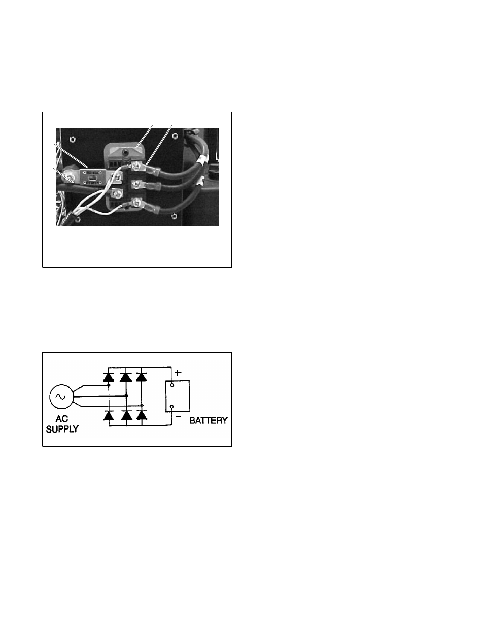
5.2 Circuit Protection
A fuse on the output (DC) side of the voltage rectifier
interrupts the generator output in the event of a 50%
overload or a short circuit in the wiring between the
generator and the load. See Figure 5-5. Replace the
fuse if it blows. See Maintenance and Service Parts in
the Introduction of this manual for the fuse part number.
3
4
1
6092-33
1. Voltage rectifier
2. AC input side (stator leads)
3. DC output side (output leads)
4. Output fuse
2
Figure 5-5
Voltage Rectifier and Fuse
5.3 Voltage Rectifier
The voltage rectifier converts AC voltage from the
alternator into DC voltage.
Figure 5-6 shows the
rectifier schematic.
Figure 5-6
Rectifier Schematic
If there is no DC voltage at the output connector, check
the fuse (see Figure 5-5). Test for output at the rectifier
to check the output leads. Check for AC voltage into the
rectifier. If there is AC voltage coming into the rectifier,
but no DC output, replace the rectifier. The voltage
rectifier has no adjustments.
The microprocessor controller monitors the DC output
voltage. To verify accurate voltage control, increase and
decrease loads while measuring DC output voltage at
the output connector. The output voltage should remain
fairly steady at the rated voltage as the engine speed
increases or decreases in response to load changes.
If voltage falls below the rated value as load increases or
decreases, check for the following problems:
D
Inadequate fuel supply
D
Fuel solenoid malfunction
D
Fuel metering valve malfunction
D
Stepper motor/throttle linkage binding
5.4 Electronic Governor
The system uses a variable-speed generator to
maintain the rated output voltage with varying loads.
The governor system regulates the engine speed with
changing loads.
The governor system consists of an electronic governor
control and an electromechanical actuator. Leads AC1
and AC2 provide a speed (frequency) signal from the AC
side of the voltage rectifier (terminals E and C) to the
control board. The control board signals the actuator,
which controls the throttle and hence the engine speed,
to maintain the generator nominal output voltage.
5.4.1
Governor Checks
The factory-set electronic governor does not normally
require adjustment. If the engine operates erratically,
check the following connections and conditions before
adjusting the governor:
D
Check the electrical connections and wire harnesses
for clean, tight connections.
D
Check the speed-sensing connections at rectifier
terminals C and E. Poor connections may cause an
erratic signal, which could cause the unit to shut
down.
D
Check the electrical ground connections.
D
Check the battery connections.
Verify that the
connections are clean and tight.
D
Check for a good positive 12-volt DC supply. Also
check if the positive voltage supply is unstable or