5 ignition system, 1 ignition trigger – Alpha Technologies AlphaGen 3.5_5.0kW Kohler COM5 User Manual
Page 45
TP-6482 8/06
45
Section 5 Component Testing and Adjustment
3. Reconnect the battery. The stepper motor should
move clockwise to the closed-throttle position with
a noticeable clicking sound. If the stepper motor
does not stay in the closed-throttle position,
replace the stepper motor.
Only two stepper motor leads of each coil group are
utilized (BLACK-YELLOW and RED-WHITE).
The
resistance per phase is 38.5 ohms. See Figure 5-10.
BLK
YEL
GRN
RED WHT
BLU
SB555
Figure 5-10 Actuator Coil Group
5.5 Ignition System
The breakerless ignition system includes a battery
ignition coil, electronic ignition module, and an ignition
trigger coil.
See Figure 5-11.
The ignition module
electronically interrupts battery voltage to the primary
coil winding, inducing high voltage in the secondary
winding and producing the spark at the spark plug.
1. Flywheel magnet
2. Ignition trigger
3. Ignition module
4. Run relay (not replaceable)
5. Spark plug
6. Ignition coil
tp6092
+
B
C
G
W
BLK
BATT +
1
2
3
4
6
5
Figure 5-11 Ignition System
Check the continuity of the spark plug lead. Check the
condition of the lead insulation and spark plug boot.
Refer to Section 3.8.2 for additional spark plug
information.
Figure 5-12 shows some ignition specifications.
Item
Specification
Trigger gap
1.02 mm (0.040 in.)
Trigger coil resistance:
Part no. GM17721
Part no. GM23592
190--205 ohms
320--360 ohms
Timing
28
° BTDC
Spark plug gap
0.76 mm (0.030 in.)
Figure 5-12 Ignition System Specifications
5.5.1
Ignition Trigger
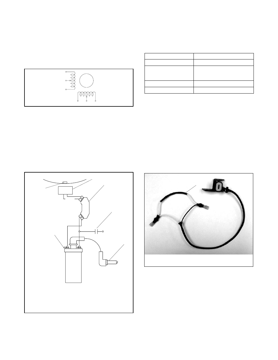
Two types of trigger coils are used. One type, part
number GM17721, has a resistor connected to the
trigger coil cable. See Figure 5-13. Use trigger coil
GM17721 only with ignition module 278903. The other
coil, GM23592, has no resistor in the wiring. The ignition
module part number is stamped on the back of the
module. Use coil GM23592 only with ignition module
GM23591, which has an internal resistor.
See
Section 5.5.2 for more information on ignition modules.
1
tp6092
1. Resistor, used on GM17721 only.
Figure 5-13 Trigger Coil GM17721 (use with ignition
module 278903)
Use an ohmmeter to check trigger coil resistance and
compare the measured value to resistances shown in
Figure 5-12. An open coil will produce a reading of
470 ohms. If trigger coil is open or shorted, replace it.