3 service access – Alpha Technologies AlphaGen 3.5_5.0kW Kohler COM5 User Manual
Page 23
TP-6482 8/06
23
Section 3 Scheduled Maintenance
3.3 Service Access
Use the following procedure to gain access to the
generator set for maintenance or service.
See
Figure 3-2 and Figure 3-3.
A key is required to open the enclosure. Obtain the
enclosure key from the equipment owner.
Use the
following procedure to gain access to the generator set
for maintenance or service. See Figure 3-3.
Refer to the enclosure manufacturer’s instruction
manual for more information.
Note: Allow the exhaust system to cool before
disconnecting the exhaust pipe.
Inspect the
exhaust gasket and replace it if necessary when
reassembling the exhaust system. See the list of
routine service parts in the Introduction of this
manual for the gasket part number.
Generator Set Service Access
1. Remove the front door of the cabinet.
2. Place the generator set master switch in the STOP
position.
3. Remove the front panel from the generator set
compartment.
4. Disconnect the generator set battery harness,
engine wiring harness, and load leads at the quick-
disconnect plugs.
5. Turn off the fuel supply at the upstream valve and
disconnect the fuel line on the right side of the
cabinet. See Figure 3-3.
1. Exhaust connection
1
GM14140B-AL
+
--
+
--
NG
LP
Figure 3-2
Exhaust Connection
6. Remove the back panel of the cabinet to gain
access to the exhaust connection near the bottom
of the unit.
7. Disconnect the engine exhaust pipe at the location
show in Figure 3-2.
8. Grasp the generator tray at the sides and pull the
generator set forward.
9. Remove the four bolts securing the generator set to
the enclosure rails.
Use appropriate lifting
equipment to lift the generator set off the rails. The
generator
set
weighs
approximately
68 kg
(150 lb.).
Note: Service fixtures are required to run the generator
set outside the enclosure. Refer to Section 5.1 for
instructions and precautions.
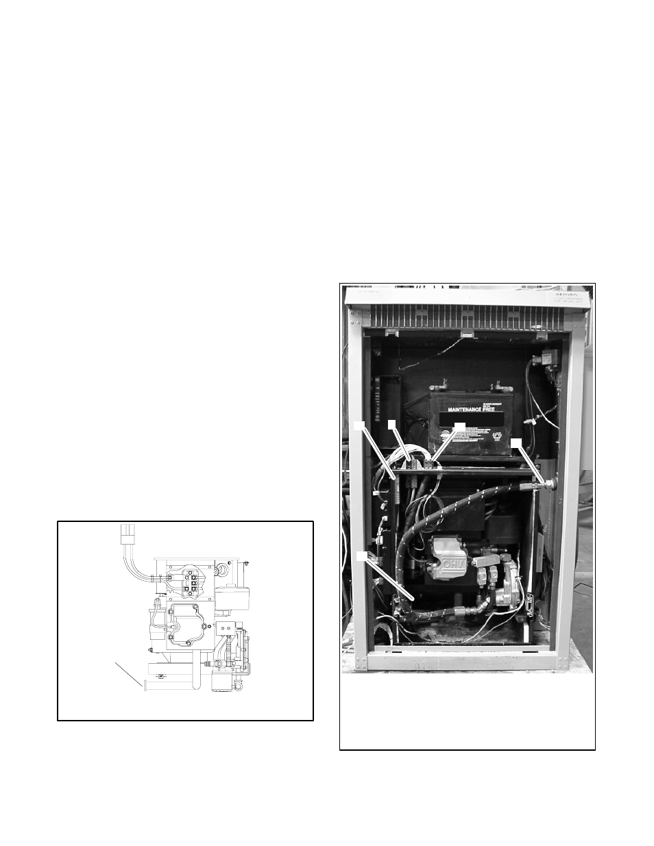
3
1. Load lead connector
2. Battery harness connector
3. Engine harness connector
4. Fuel connection
5. Exhaust pipe connection (not visible in this photo)
2
4
5
1
TP6076
Figure 3-3
Generator Set Installed in Cabinet
(door and front panel removed)