2 control connections, 3 fault shutdowns, 1 generator set master switch – Alpha Technologies AlphaGen 3.5_5.0kW Kohler COM5 User Manual
Page 56: 2 remote start/stop connections, 3 status indicators
TP-6482 8/06
56
Section 6 Controller Operation and Test
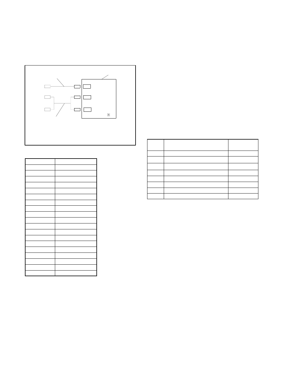
6.2 Control Connections
Wiring harnesses connect the generator set control
board to the system remote controls and the engine.
Figure 6-2 shows the wiring harness connections to the
control board. See the wiring diagrams in Section 8 for
pinouts and connection details. Figure 6-3 defines the
abbreviations used in the wiring diagrams.
M-337000C-B
1. Generator set to remote control system
interface harness, GM14245
2. Generator set control circuit board
3. Engine interface harness, GM14244
1
3
P1
P2
P3
R37
2
P3
P1
P6
P1
J4
P5
P2
Figure 6-2
Generator Set Control Connections
Abbreviation
Definition
N
Ground
OVC
Overcrank
N/C
Not connected
STT
Start
LOP
Low oil pressure
STP
Stop
OVT
Overtemperature
OVS
Overspeed
DCP
DC output sensing
DCN
DC output sensing
AC1
AC speed sensing
AC2
AC speed sensing
M1
Throttle control
M2
Throttle control
M3
Throttle control
M4
Throttle control
P
Battery
70
Run
71
Crank
Figure 6-3
Pin Abbreviations
6.2.1
Generator Set Master Switch
Some models use a 3-position generator set master
switch. Set the switch to the AUTO position for remote
operation. Set both the generator set master switch and
the remote switch to the STOP or OFF position and
disconnect the engine starting battery before servicing
the generator set.
Other models use a momentary start/stop generator set
switch that returns to the center position when released.
Be sure to set the remote switch to the OFF position
before servicing the generator set. Hold the generator
set master switch in the STOP position while
disconnecting the starting battery.
6.2.2
Remote Start/Stop Connections
For remote operation, connect a three-wire remote
start/stop switch to P6 of the interface harness. To start,
open a contact between pins 6 and 7 and close a contact
between pins 5 and 6 of connector P6 (see the wiring
diagrams). To stop, close the contact between pins 6
and 7 and open the contact between pins 5 and 6.
6.2.3
Status Indicators
Eight LEDs on the generator set control board indicate
the system status conditions and fault shutdowns listed
in Figure 6-4. Figure 6-1 shows the LED locations.
LED
Indicates
Remote
Annunciation
1
Overspeed shutdown
Yes
2
Overtemperature shutdown
Yes
3
Engine running status indicator
Yes
4
Low oil pressure fault shutdown
Yes
5
Overcrank shutdown
Yes
6
Fuel valve energized
No
7
Cranking energized
No
8
Common fault indicator
No
Figure 6-4
Control Board LEDs
6.3 Fault Shutdowns
The generator set shuts down automatically under the
fault conditions listed in Figure 6-5 and cannot be
restarted until the controls are reset. Correct the fault
condition and then reset the controller by placing either
the remote control switch or the generator set master
switch in the STOP position.
The high engine
temperature fault automatically resets when the
generator set cools.
Refer to the troubleshooting charts in Sections 4 to
further diagnose the cause of a fault shutdown.