Alpha Technologies AlphaGen 3.5_5.0kW Kohler COM5 User Manual
Page 51
TP-6482 8/06
51
Section 5 Component Testing and Adjustment
8. Clean the hose fitting with a dry cloth or brush,
apply fresh pipe sealant, and install it into the LP (or
natural gas) inlet.
9. Slide the hose onto the hose fitting and secure it
with the clamp.
10. Turn on the fuel supply and check for leaks using a
gas leak detector.
11. Reconnect the battery harness.
12. Install the generator compartment front panel. Set
the generator set master switch to the AUTO or
center position to return the generator set to
standby service.
13. Replace the enclosure door.
5.7.4
Fuel System Recalibration
The fuel metering valves are factory-set to meet
emissions requirements and sealed to discourage field
adjustments. If the fuel system requires recalibration,
only trained, authorized service technicians may adjust
the fuel metering valves. Always use an oxygen sensor
and an exhaust tube with an oxygen sensor port,
available from the generator set manufacturer, when
adjusting the fuel metering valves.
Note: Changing the fuel system adjustments may void
the emissions certification.
Fuel
system
recalibration requires
the following
equipment, which is available from Kohler Co.:
D
Oxygen sensor
D
Test exhaust pipe with oxygen sensor port
See Maintenance and Service Parts in the Introduction
section of this manual for the equipment part numbers.
Follow the instructions in Section 5.1 to remove the
generator set and operate outside the enclosure.
Fuel System Recalibration Procedure
1. Run the generator set at full load and check the
oxygen sensor reading. At full load, the oxygen
sensor
output
voltage
should
be
between
0.75 VDC and 0.85 VDC.
2. If adjustment is required, remove seal on the fuel
metering valve and adjust the valve to obtain an
oxygen sensor reading between 0.75 VDC and
0.85 VDC. See Figure 5-20 for the fuel metering
valve location.
3. Reseal the valve after adjustment.
1
tp6092
1. Oxygen sensor
2. Exhaust tube GM23580
2
Figure 5-23 Exhaust Tube and Oxygen Sensor
5.7.5
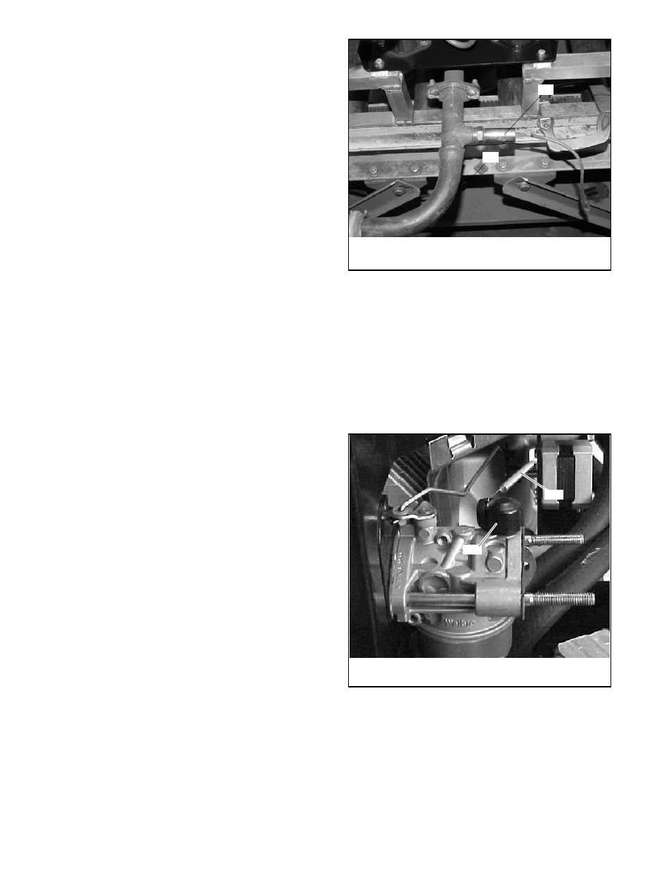
Choke
Some engines are equipped with a choke, which is held
open at all times by the choke spring shown in
Figure 5-24.
If the engine is equipped with a choke, identified by the
knob shown in Figure 5-24, check that the spring is
attached and holding the choke open.
1
2
TP5632721
1. Choke spring
2. Choke knob
Figure 5-24 Choke Assembly (not included on all
engines)
Generator sets built after June, 2001, do not have a
choke assembly and, therefore, do not require the
spring. Choke solenoid service kit GM42302 can be
installed to improve engine starting in cold weather. See
TT-1422 for more information.