2 stepper motor check – Alpha Technologies AlphaGen 3.5_5.0kW Kohler COM5 User Manual
Page 44
TP-6482 8/06
44
Section 5 Component Testing and Adjustment
below 8 volts DC making the control unit function
erratically.
D
Check for stepper motor/throttle shaft linkage binding
or wear. The linkage arm and lever arms must not
bind or rub against other components while moving.
D
Verify that the governor stepper motor operates with
steady and smooth movement. If the movement of
the stepper motor is erratic or large changes in
movement occur, check for shaft misalignment,
linkage binding, or loose or broken wiring or plug
connections.
D
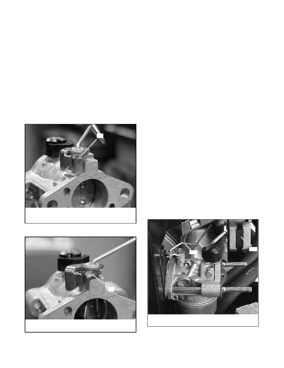
If the throttle linkage binds or otherwise does not
operate smoothly, check the bushing shown in
Figure 5-7 and Figure 5-8. The bushing has a longer
slot on one side that must be oriented as shown in
Figure 5-7.
1
tp6092
1. Bushing in the correct orientation, with long
slot facing the viewer
Figure 5-7
Correct Bushing Rotation
1
tp6092
1. Bushing in the wrong orientation
Figure 5-8
Incorrect Bushing Rotation
D
Check carburetor for dirt, grime, or misadjustment.
Also, check the idle-adjustment screw. The screw
should not prevent the throttle plate from completely
closing.
Also, check the throttle linkage for any
binding, dirt, damage, etc.
Note: Often hunting/surging problems thought to be
caused by the governor are actually linked to
carburetor adjustment.
Check the carburetor
adjustment before adjusting the governor.
The fuel shutoff solenoid deenergizes and generator set
shuts down with the following electronic governor faults:
D
Loss of pickup while running (throttle moves to closed
position)
D
Engine overspeed
D
Break of fuel shutoff solenoid lead
D
Loss of DC power to governor assembly
D
Break of stepper motor leads (erratic performance)
D
Actuator linkage failure (erratic performance)
If none of the above conditions exist, proceed to
Section 5.4.2, Stepper Motor Check.
5.4.2
Stepper Motor Check
Use the following procedure to test the operation of the
governor stepper motor.
Stepper Motor Test Procedure
1. Stop the generator set and disconnect the battery.
2. Manually
move
the
governor
linkage
fully
counterclockwise (open throttle). See Figure 5-9.
1
2
TP5632721
1. Electronic governor stepper motor
2. Carburetor throttle linkage
Figure 5-9
Stepper Motor Throttle Linkage