Display and setting elements – ABUS FUAA10021 Secvest IP Basic Set Operating instructions User Manual
Page 12
10 Display and setting elements
11
10. Display and setting elements
10.1 Display LEDs
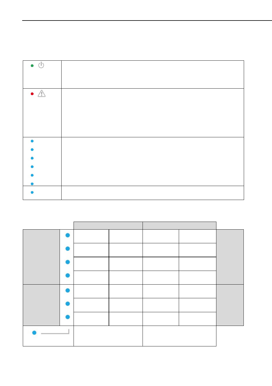
The display consists of 10 LEDs
Green LED (“Power” LED) for monitoring the power supply
• Permanently lit: Power supply is OK
• Flashing with 1 Hz: Mains power supply failure; only indicated if a
backup battery is in use.
Red LED (“Trouble” LED) for displaying faults
• Off: No faults
• Flashing with 1 Hz: Supervision fault (detector or device is
indicated by the channel LED flashing with 1 Hz. If only this LED
flashes, this indicates that the alarm centre itself has been
tampered with).
• Permanently lit: Indicates jamming.
Blue LEDs (“Channel” LEDs) for detector status display
• Off: Detector OK (closed)
• Permanently lit: Detector is open or has triggered (open);
operating units are lit briefly indicating that a wireless signal has
been received.
• Flashing with 5 Hz: Empty battery on a wireless component
• Flashing with 1 Hz: Wireless component has been tampered
Bottom blue LED lights up: Indicates that this refers to the second
caption level (i.e. channels 8–14).
10.2
LED
table
Layer 1
Layer 2
Zone 1
Lights
up/
flashes
Channel 7
Lights up/
flashes
Channel 14
Zone 3
Lights up/
flashes
Channel 6
Lights up/
flashes
Channel 13
Lights up/
flashes
Channel 5
Lights up/
flashes
Channel 12
Lights up/
flashes
Channel 4
Lights up/
flashes
Channel 11
Operating
units
(Secvest Key
remote control)
Lights
up/
flashes
Channel 3
Lights up/
flashes
Channel 10
Zone 2
Lights up/
flashes
Channel 2
Lights up/
flashes
Channel 9
Lights up/
flashes
Channel 1
Lights up/
flashes
Channel 8
Does not light up
Lights up