Installing a board in the enclosure – Extron Electronics PowerCage FOX Tx_Rx DVI Plus User Guide User Manual
Page 47
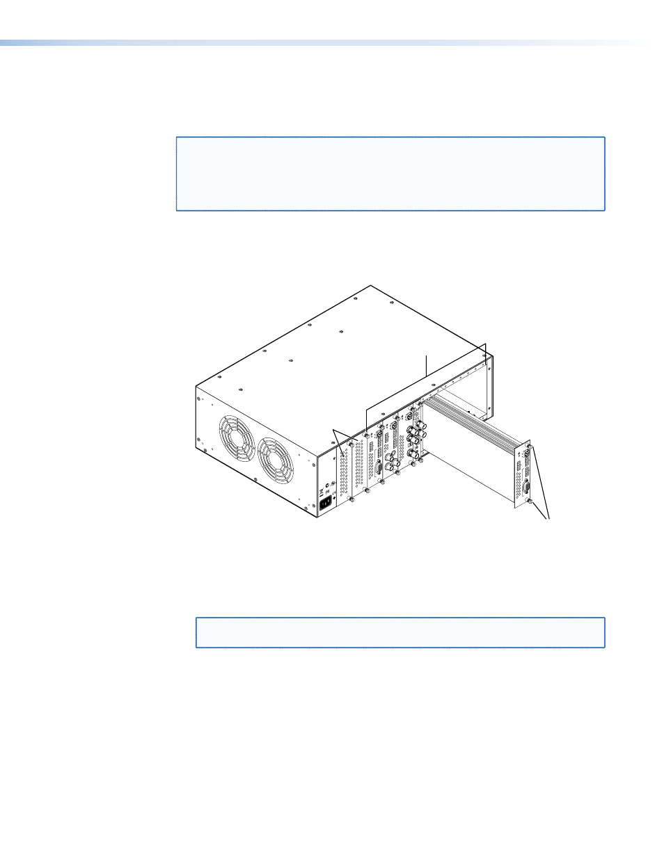
Installing a Board in the Enclosure
Up to 16 single slot or 8 dual slot input/output boards can be inserted into the PowerCage
enclosure. The PowerCage transmitters and receivers are all dual slot boards.
NOTE: The boards are hot-swappable, and can be installed or removed without
disconnecting power to the PowerCage enclosure.
Use ESD precautions when installing a board to avoid damaging the board. Keep
the board in the anti-static bag until needed. Use proper grounding techniques
during installation.
1.
Ensure power is removed from the PowerCage enclosure.
2.
Position the board in the slot so that the power and communication ports on the
front end of the board are aligned with the matching ports inside of the board cage
(see figure 27).
1
2
REM
OT
E
RS-232
RS-232
O
VER FIBER
Tx Rx
Tx
ALAR
M
Rx
OUTPUT
RGB
Po
we
rCa
ge
FO
X RX RG
B
Tx Rx
LR
A
UDIO
MONO
AU
DIO OUTPU
T
12
SHAR
P
GAIN
Y/VID
C
INPU
T
Po
we
rCa
ge
MTP R
AV
Tx
Rx
HD/SDI INPU
TH
D/SDI OUTPUTS
MODE
Po
we
rCa
ge
FO
X 3G HD-SD
I
1
2
REMO
TE
RS-232
RS-232
O
VER FIBE
R
Tx Rx
Tx
ALARM
Rx
VIDE
O
1
2
3
4
Po
we
rCa
ge
FO
X R
x A
V
Tx Rx
LR
A
UDI
O
1
2
REMO
TE
RS-232
RS-232
O
VER FIBER
Tx Rx
Tx
ALARM
Rx
OUTPUT
RGB
Po
we
rCa
ge
FO
X RX RG
B
Tx Rx
LR
A
UDIO
5A MAX.
100-240V 50/60H
z
N15
778
C
US
LIS
TED
1T2
3
I.T.
E.
Screws (2 per card)
16 available single board slots or
8 double board slots
Power
Supply
Figure 27.
Inserting Boards into the PowerCage 1600 Enclosure
3.
Carefully slide the board into the slot and push the board firmly into place.
4.
Use a screwdriver to tighten the 2 screws to secure the board into place.
5.
Repeat steps 2 to 4 for all boards needing installation.
NOTE: Ensure the boards are flush with the rear of the enclosure and the screws
tightened securely before applying power.
PowerCage FOX DVI and PowerCage FOX VGA • Reference Information
42