Powercage front panel port, control, and, Indicators, Figure 11. powercage front panel – Extron Electronics PowerCage FOX Tx_Rx DVI Plus User Guide User Manual
Page 19
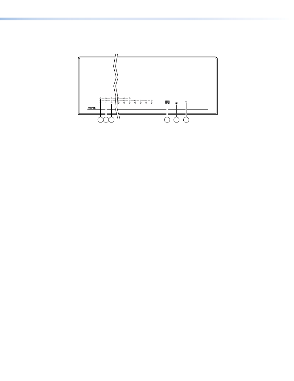
PowerCage Front Panel Port, Control, and Indicators
The following features are on the front panel of the PowerCage enclosure.
PowerCage 1600
COMM
1
POWER
ALARM
2
3
14
15
16
1
PSU
2
PSU
1
FAN
2
FAN
COMM
SELECT
CONFIG
TEMP
13
16
17
18
14 15
Figure 11.
PowerCage Front Panel
m
Comm LED (16 board locations) — This LED lights to indicate that the board at this
location is selected for connection to the Configuration port (item
q
). Repeatedly press the
Comm Select button (item
p
) as necessary to select the desired board.
n
Power LED (all locations) — This LED lights to indicate that power is applied to the device
at this location.
o
Alarm LED (16 board locations) — This LED lights to indicate that light is not received on
the Rx connector of the board at this location.
Alarm LED (2 PS locations) — This LED lights to indicate that the power supply has failed
or is out of tolerance.
Alarm LED (2 Fan locations) — This LED lights to indicate that the fan has failed.
p
Comm Select button — Repeatedly press this button as necessary to select the desired
board for connection to the Configuration port (item
q
). The Comm LED (item
m
) for the
selected board lights.
PowerCage FOX DVI and PowerCage FOX VGA • Installation and Operation
14