Extron Electronics PowerCage FOX Tx_Rx DVI Plus User Guide User Manual
Page 32
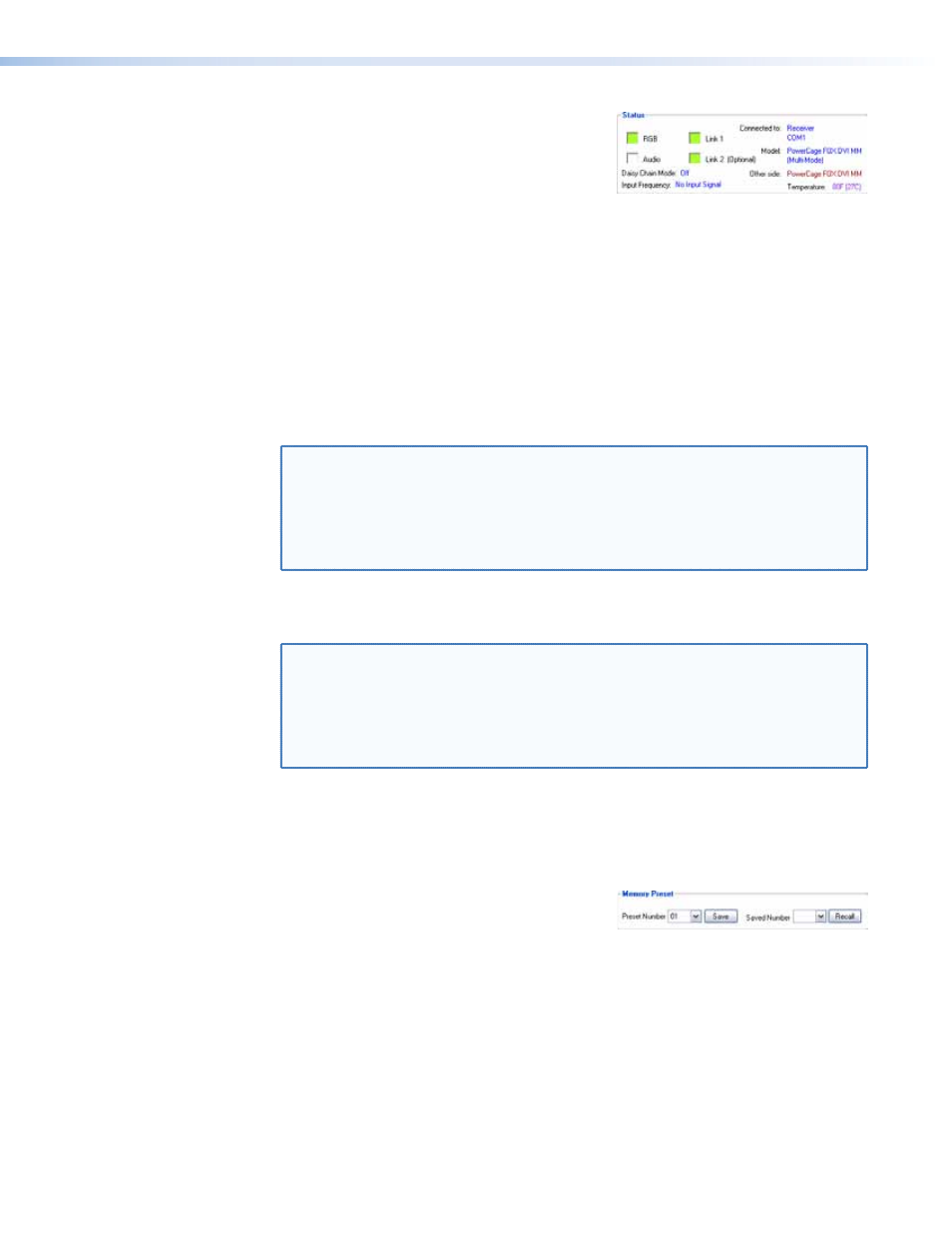
Status area
The Status area provides visual indications of the
connection status.
•
RGB indicator — This indicator is green when
the transmitter detects a sync signal on its video input:
•
Horizontal sync (H) (for RGBHV video)
•
Composite sync (S) (for RGBS video)
•
Green (Sync on green) (G) (for RGsB or RsGsBs video)
•
DVI video
•
Audio indicator — This indicator is green when the transmitter detects a low level
audio signal for a short period. This indicator goes dark if the audio signal drops below
the minimum threshold for a short period.
•
Link 1 indicator — This indicator is green when the receiver detects light on the fiber
optic cable connected to the Tx port.
NOTE: The receiver detects the transmitter-Tx-to-receiver-Rx light. It reports the
status to the transmitter via the optional Rx cable.
If the PC is connected to the transmitter and either the secondary (receiver-
Tx-to-transmitter-Rx) cable is not connected in your system or the receiver
is in the daisy chain mode, the Link 1 indicator in the control program
does not show green (detected), whether the receiver detects the link or not.
•
Link 2 (Optional) indicator — This indicator is green when the transmitter detects
light on the fiber optic cable connected to the Rx port.
NOTE: The transmitter detects the receiver-Tx-to-transmitter-Rx light. It reports the
status to the receiver via the Tx cable.
If the PC is connected to the receiver and either the primary (transmitter-
Tx-to-receiver-Rx) cable is disconnected or the receiver is in the daisy chain
mode, the Link 2 indicator in the control program will not show green
(detected), whether the transmitter detects the link or not.
The Status area also shows which unit the controlling PC is connected to, the
PowerCage FOX model (multimode or singlemode), the internal temperature, the daisy chain
mode, and the video input frequency. The “Other Side” entry is the device connected to the
far end of the fiber optic cable.
Memory Preset area
The Memory Preset area provides a means to
save and recall memory presets. Memory presets
are stored values of the horizontal and vertical position and sizing information saved in
nonvolatile memory. When the PowerCage FOX is powered down and later powered back
up, the settings are available for selection using the Recall button. Saving the settings to a
preset using the Save button overwrites the settings previously written to that preset.
PowerCage FOX DVI and PowerCage FOX VGA • Remote Control
27