Installation and operation, Mounting the units, Connections and indications – Extron Electronics PowerCage FOX Tx_Rx DVI Plus User Guide User Manual
Page 12: Mounting the units connections and indications, Figure 2. powercage fox tx transmitter connectors
Installation and
Operation
This section describes the installation and operation of the PowerCage FOX VGA and
PowerCage FOX DVI, including:
•
•
•
PowerCage Front Panel Port, Control, and Indicators
•
Mounting the Units
The PowerCage FOX transmitter or receiver must be installed in an Extron PowerCage
enclosure (see “
Installing a Board in the Enclosure
Connections and Indications
PowerCage
FOX Tx VGA
Transmitters
Receivers
PowerCage
FOX Tx DVI
1 2
REMO
TE
RS-232
RS-232
O
VER FIBER
Tx Rx
Tx
ALARM
Rx
INPUT
RGB
PowerCage
FOX Tx VGA
Tx Rx
LR
A
UDIO
1 2
REMO
TE
RS-232
RS-232
O
VER FIBER
Tx Rx
Tx
ALARM
Rx
INPUT
DV
I
PowerCage
FOX Tx DVI
Tx Rx
LR
A
UDIO
PowerCage
FOX Rx VGA
PowerCage
FOX Rx DVI
1 2
REMO
TE
RS-232
RS-232
O
VER FIBER
Tx Rx
Tx
ALARM
Rx
OUTPUT
RGB
PowerCage
FOX Rx VGA
Tx Rx
LR
A
UDIO
1 2
REMO
TE
RS-232
RS-232
O
VER FIBER
Tx Rx
Tx
ALARM
Rx
OUTPUT
DV
I
PowerCage
FOX Rx DVI
Tx Rx
LR
A
UDIO
6
6
7
7
5
5
4
4
2
1
3
3
6
6
8
8
5
5
4
4
12
12
12
12
10
9
11
11
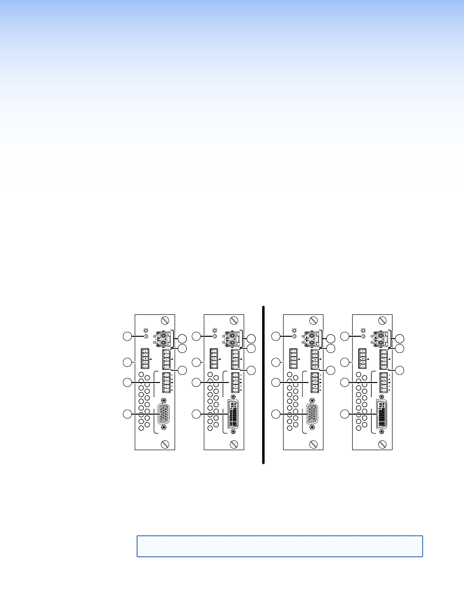
Figure 2.
PowerCage FOX Tx Transmitter Connectors
a
VGA Input connectors (PowerCage FOX VGA only) — Connect an analog
VGA-UXGA RGB video source to this 15-pin HD female connector.
b
DVI-I Input connector (PowerCage FOX DVI only) — Connect a single link
of DVI-D to this DVI-I connector (see “
DVI connector (PowerCage FOX DVI)
“ on
page 12 for pin assignments.)
NOTE: The PowerCage FOX DVI accepts only the digital signals on the DVI-I Input
connector. The analog pins on the port are not connected.
PowerCage FOX DVI and PowerCage FOX VGA • Installation and Operation
7