E 3, above, and, Figure 7 – Extron Electronics PowerCage FOX Tx_Rx DVI Plus User Guide User Manual
Page 16
i
VGA Output connector (PowerCage FOX Rx VGA only) — Connect an analog
VGA-UXGA RGB video display to this 15-pin HD female connector.
NOTE: You can set the receiver to output the desired video format: RGBHV or
RGsB. RGBHV is the default (see the “
”section.)
j
DVI-I Output connector (PowerCage FOX DVI only) — Connect a DVI video
display to this DVI-I connector (see “
DVI connector (PowerCage FOX DVI)
“ on
page 12 for pin assignments.)
NOTE: The PowerCage FOX DVI outputs only the digital signals on the DVI-I Output
connector. The analog pins on the port are not connected.
k
Audio output connector (receivers) —
This 5-pole, 3.5 mm captive screw
connector outputs the transmitted, unamplified, line level audio. Connect audio devices,
such as an audio amplifier or powered speakers.
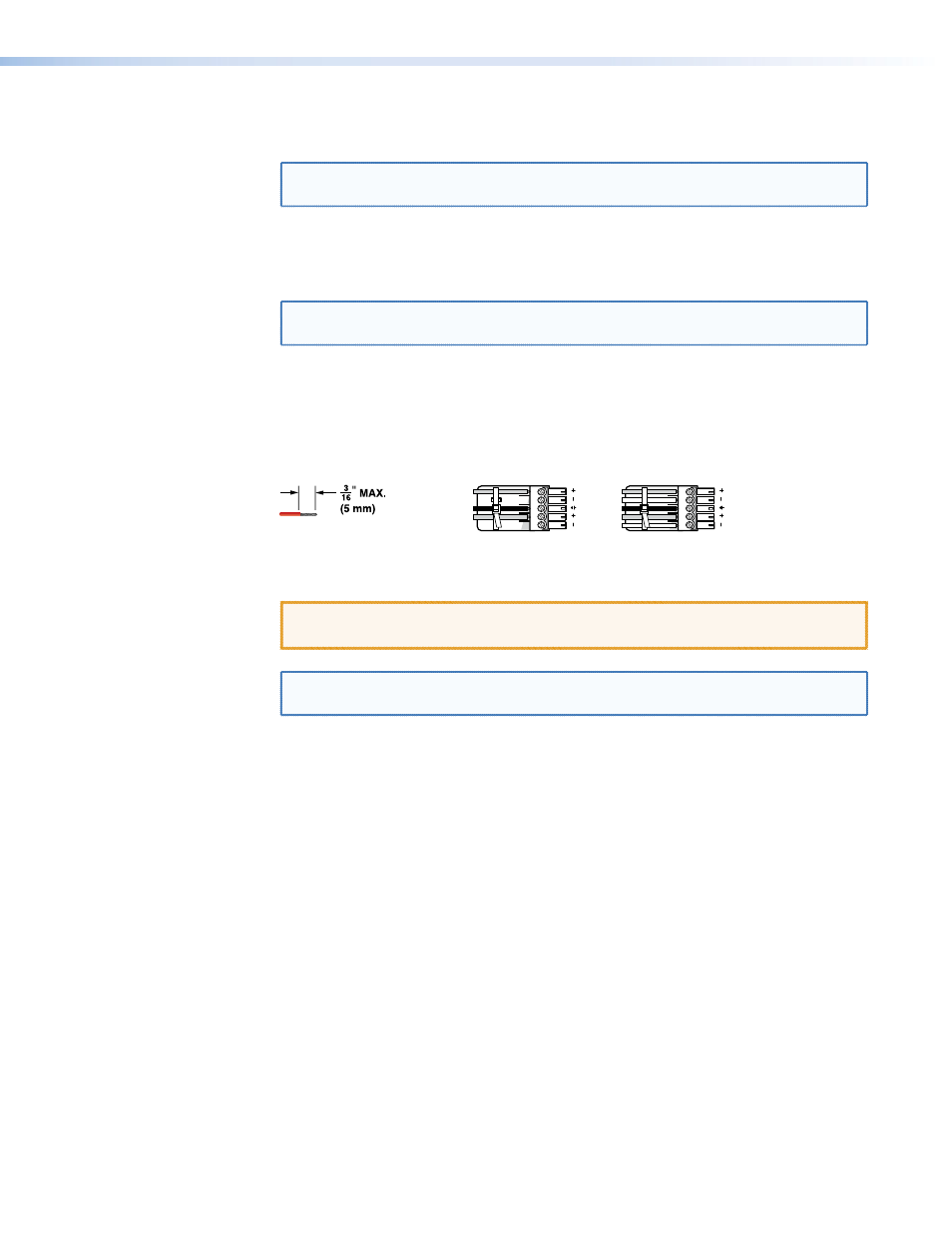
See figure 7 to properly wire a captive screw output connector. Use the supplied tie-
wrap to strap the audio cable to the extended tail of the connector.
Ring
Sleeve(s)
Tip
Tip
Ring
Sleeve(s)
Tip
Tip
Unbalanced Stereo Output
Balanced Stereo Output
NO GROUND HERE.
NO GROUND HERE.
LR
Do not tin the wires!
Figure 7.
Captive Screw Connector Wiring for Stereo Audio Output
CAUTION: For unbalanced audio, connect the sleeves to the ground contact.
DO NOT connect the sleeves to the negative (-) contacts.
NOTES: The length of exposed wires is critical. The ideal length is 3/16 inch (5 mm)
(see the audio input connector
on page 8 for more information.)
The volume level for the output can be set to either the consumer line level (-10 dBV)
or the professional line level (+4 dBu) via RS-232 control (see the “
section for details.)
l
Power LED — This LED lights to indicate that power is applied to the unit.
PowerCage FOX DVI and PowerCage FOX VGA • Installation and Operation
11