Extron Electronics PowerCage FOX Tx_Rx DVI Plus User Guide User Manual
Page 13
c
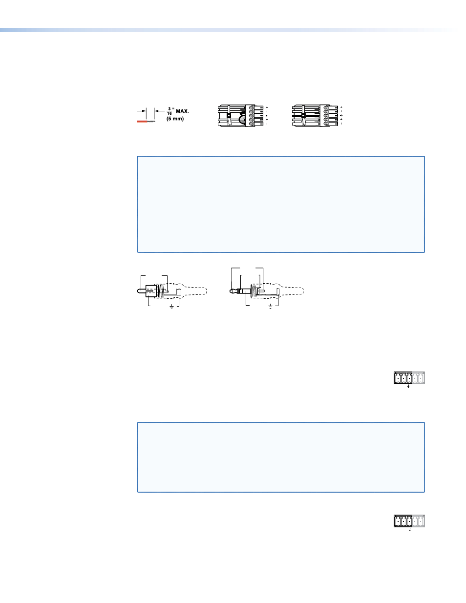
Audio Input connector (transmitters) — Connect a balanced or unbalanced
stereo or mono audio input to this connector. The connector is included with
transmitter, but you must supply the audio cable (see figure 3 to wire a captive screw
connector for the appropriate input type and impedance level.) Use the supplied tie-
wrap to strap the audio cable to the extended tail of the connector.
LR
Unbalanced Stereo Input
Balanced Stereo Input
Ring
Sleeve (s)
Tip
Sleeve
Tip
Sleeve
Tip
Tip
Ring
Do not tin the wires!
Figure 3.
Captive Screw Connector Wiring for Stereo Audio Input
NOTES: • The length of exposed wires is critical. The ideal length is 3/16 inch (5 mm).
•
If the stripped section of wire is longer than 3/16 inch, the exposed
wires may touch, causing a short circuit.
•
If the stripped section of wire is shorter than 3/16 inch, wires can be
easily pulled out even if tightly fastened by the captive screws.
• Figure 4 identifies the tip, ring, and sleeve. A mono audio connector
consists of the tip and sleeve. A stereo audio connector consists of the
tip, ring and sleeve. The tip, ring, and sleeve wires are also shown on the
captive screw audio connector diagrams, figure 3, above, and
.
Tip (+)
Sleeve ( )
Sleeve ( )
Ring (-)
Tip (+)
RCA Connector
3.5 mm Stereo Plug Connector
(balanced)
Figure 4.
Typical Audio Connectors
The input audio level can be set via RS-232 control (see the “
d
RS-232 Over Fiber port — If you want the transmitter/receiver system to
RS-232
OVER FIBER
Tx Rx
pass serial command signals between the transmitter and receiver, for serial
control of a projector for example, connect the host device to the transmitter
and the slave device to the receiver via the first three poles on the left (Tx,
Rx, and _) of these 5-pole captive screw connectors on both units (see “
“ on page 13 to wire this connector.
NOTES: • If you connect only one fiber optic cable (
), or you configure the
receiver for daisy-chaining, you will not receive reports from the controlled
device. To receive responses from the controlled device, you must install
two fiber optic cables and leave the receiver in normal mode (via an SIS
command for the PowerCage FOX Rx receiver.)
• The PowerCage FOX can pass RS-232 commands and responses at rates
up to 115200 baud.
e
Remote RS-232 port —
For serial control of the transmitter and receiver,
1 2
REMOTE
RS-232
Tx Rx
ALARM
connect a host device, such as a computer, to either unit via three poles
(Tx, Rx, and _) of this 5-pole captive screw connector on either unit (see
“
“ on page 13 to wire this connector.)
See “
“ for definitions of the SIS commands (serial commands to
control the transmitter via this connector).
PowerCage FOX DVI and PowerCage FOX VGA • Installation and Operation
8