Remote control, Rgsb. rgbhv is the default (see the, Sis commands – Extron Electronics PowerCage FOX Tx_Rx DVI Plus User Guide User Manual
Page 26: Or the fox extender, Simple instruction set control, Command/response table for sis commands
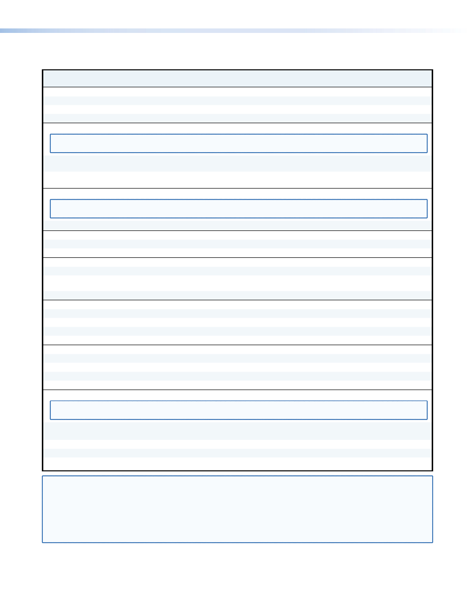
Command
ASCII Command
(host to unit)
Response
(unit to host)
Additional description
Video mute
Mute output
1B
Blk1
]
Blank the video output.
Unmute output
0B
Blk0
]
Output video.
Show video mute status
B
X!]
Video mute status is
X!
.
Display Data Channel (DDC) resolution and rate (systems with DVI receivers only)
NOTE: If the receiver is a FOX 500, the rear panel DDC Resol(ution) rotary switch on the transmitter must be in position 1 for the
variables to be changeable via an SIS command. The unit returns the E14 error if the switch is in other than position 1.
Set DDC resolution and
rate
41*
X@
*
X#
#
DDC
X@
*
X#]
Select a DDC resolution and refresh rate.
Show DDC resolution and
rate
41#
X@
*
X#]
Show the DDC resolution and refresh rate.
Mode switch position (systems with FOXBOX receivers only)
NOTE: Only DIP switch 1 (the first
X$
) has any effect on the system operation. When the switch is on (up), the receiver is in daisy chain
mode.
Show DIP switch position
8#
X$X$]
Show the FOXBOX receiver DIP switch position.
Output sync format
Set output sync format
6*
X%
#
Syn
X%]
Set the sync format.
Show output sync format
6#
X%]
Output sync polarity
Set output polarity negative
7*1#
Pol1]
Force the receiver output to always be negative.
Set polarity to the input
7*0#
Pol0]
Polarity follows the video sync input to the
transmitter.
Show output sync polarity
7#
X^
]
Horizontal shift
Set a horizontal position
X&
H
Hph
X&]
Set horizontal centering to
X&
.
Increment position
+H
Hph
X&]
Shift the image one pixel to the right.
Decrement position
–H
Hph
X&]
Shift the image one pixel to the left.
Show position
H
X&]
Vertical shift
Set a vertical position
X&
/
Vph
X&]
Set vertical centering to
X&
.
Increment position
+/
Vph
X&]
Shift the image down one line.
Decrement position
–/
Vph
X&]
Shift the image up line.
Show position
/
X&]
Horizontal start
NOTE: When the controlling PC is connected to the receiver, the PowerCage FOX can perform this command only if the receiver-Tx-to-
transmitter-Rx fiber cable is connected. The unit returns the E14 error if the Rx fiber is not connected.
Set a start position
X*
)
Hst
X*]
Set the horizontal location of the first active pixel.
Example:
128)
Hst128
]
Set pixel 128 as the first active pixel.
Increment start position
+)
Hst
X*]
Increase the horizontal start location value.
Decrement start position
–)
Hst
X*]
Decrease the horizontal start location value.
Show start position
)
X*]
Command/Response Table for SIS Commands
NOTE:
X!
= Mute status
0 = off
1 = on
X@
= Resolution
01 through 19. See
.
X#
= Refresh rate
1 = 50 Hz
2 = 60 Hz
X$
= Mode switch position
0 = off (down)
1 = on (up)
X%
= Output sync format
0 = RGBHV
1 = RGsB
X^
= Output sync polarity
0 = follows input
1 = force sync negative
X&
= Horizontal and vertical position
000 through 255
X*
= Horizontal start
000 through 255
PowerCage FOX DVI and PowerCage FOX VGA • Remote Control
21