Remote control, Serial ports, Board remote rs-232 ports – Extron Electronics PowerCage FOX Tx_Rx DVI Plus User Guide User Manual
Page 21
Remote Control
This section describes the remote control operation of the PowerCage FOX DVI and
PowerCage FOX VGA, including:
•
•
Simple Instruction Set Control
•
Serial Ports
The transmitter and receiver boards each have an RS-232 serial port on a 3-pin captive
screw connector that can be connected to a host device such as a computer running the
HyperTerminal utility, an RS-232 capable PDA, or a control system. The PowerCage enclosure
has a Configuration port, a 2.5 mm mini stereo jack, that parallels the board ports. These
ports make serial control of the transmitter and receiver possible.
The protocol for all ports is as follows:
•
9600 baud
• no parity
• 8 data bits
•
1 stop bit
• no flow control
NOTES: • For each unit, the Remote RS-232 port is active only if the PowerCage
Configuration port is not active. If an active Configuration port connection is
made, the Remote RS-232 port for that board becomes inactive.
• Only one fiber optic cable, transmitter-Tx-to-receiver-Rx, is required for
video, audio, and serial command transmission. However, if you connect
only one fiber optic cable, you will not receive RS-232 reports from the
controlled device, and there will be reduced RS-232 command and control
program functionality on the Rx unit. To receive responses from the controlled
device and for full functionality, install both fiber optic cables and leave the
PowerCage FOX receiver in normal configuration (via an
for
the PowerCage FOX Rx receiver).
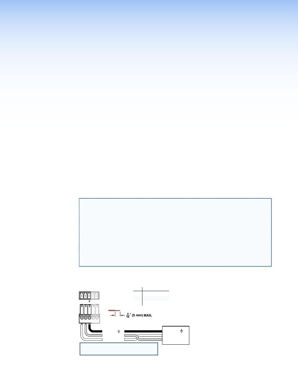
Board Remote RS-232 Ports
Do not tin the wires!
Controlling
Device
Ground ( )
Receive (Rx)
Transmit (Tx)
Ground ( )
Receive (Rx)
Transmit (Tx)
Bidirectional
Function
Pin
TX
RX
Gnd
Transmit data
Receive data
Signal ground
1 2
REMOTE
RS-232
Tx Rx
ALARM
NOTE: Cross the Tx and Rx lines once
between the source and the target.
Figure 13.
Remote Connector Pin Assignments
PowerCage FOX DVI and PowerCage FOX VGA • Remote Control
16