Making connections, Of dvi-d to this dvi-i connector (see, Dvi connector (powercage fox dvi) – Extron Electronics PowerCage FOX Tx_Rx DVI Plus User Guide User Manual
Page 17: Display to this dvi-i connector (see
Making Connections
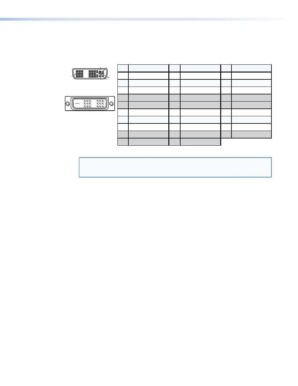
DVI connector (PowerCage FOX DVI)
Figure 8 defines the DVI pin assignments.
Pin
Signal
1
TMDS data 2–
TMDS data 2+
TMDS data 1–
TMDS data 1+
DDC clock
+5 V power
DDC data
TMDS clock+
Ground (+5 V)
No connection
TMDS clock–
Hot Plug Detect
TMDS data 0–
TMDS data 0+
Spare
Spare
Spare
Spare
Spare
Spare
TMDS data 2 shield
TMDS data 1 shield
TMDS data 0 shield
Pin
Pin
Signal
Signal
2
9
10
17
4
12
20
5
13
21
6
14
22
7
15
23
8
16
24
18
3
11
19
Male Connector
Female Connector
1
9
8
17
24 C3 C4
C1 C2
C5
C3
C4
C1
Analog Red Video
C2 Analog Green Video
C5
Analog Blue Video
Analog H. Sync
Analog Ground
Figure 8.
DVI Connectors
NOTE: The missing pins on the included DVI cable are not required for the single link of
DVI-D data supported by the PowerCage FOX DVI. The analog video pins are not
connected. All of these unused pins are shaded gray in the figure above.
DVI signals run at a very high frequency and are especially prone to errors caused by bad
video connections, too many adapters, or excessive cable length. To avoid the loss of an
image or jitter, follow these guidelines:
•
Do not exceed 16.4 feet (5 meters) on the input or buffered loop-through of the
PowerCage FOX DVI transmitter or the output of the PowerCage FOX DVI receiver.
•
Use only the cable designed for DVI signals that is supplied by Extron.
•
Limit or avoid the use of adapters.
•
Use only cables specifically intended for DVI or HDMI
®
signals. Use of non-DVI or non-
HDMI cables or modified cables can result in a missing video output.
PowerCage FOX DVI and PowerCage FOX VGA • Installation and Operation
12