About the mkp 2000 remote control panel, Rs-232 connection to the switcher, Ethernet connection to the switcher – Extron Electronics MKP 2000 User Manual
Page 8: Application diagram, Introduction
MKP 2000 Remote Control Panel • Introduction
MKP 2000 Remote Control Panel • Introduction
Introduction
This manual provides installation and operation instructions for
the Extron MKP 2000.
About the MKP 2000 Remote Control Panel
The MKP 2000 is a network-ready remote control panel that can
control any Extron matrix switcher. The MKP’s RS-232 ports
allow it to communicate with other devices (another MKP or a
matrix switcher) locally and its Ethernet port allows it to
communicate with multiple devices.
An MKP 2000 user can remotely create ties by specifying an
input and then an output to be tied to the input. The MKP can
also be dedicated to a specific group of inputs and outputs
when configured using the built-in Web pages.
The MKP 2000 panel is mounted in a two-gang wall plate that
can be installed in a wall, conference table, podium, or other
convenient location.
The matrix switcher system can have up to 128 inputs and 128
outputs. However, for example, a conference room may have
three input devices and two output devices; a training room
next door may have four input devices and one output device;
and so on. Typically, each room will have one or more MKP
control panels assigned to it, with each MKP limited to the
inputs and outputs that it can control.
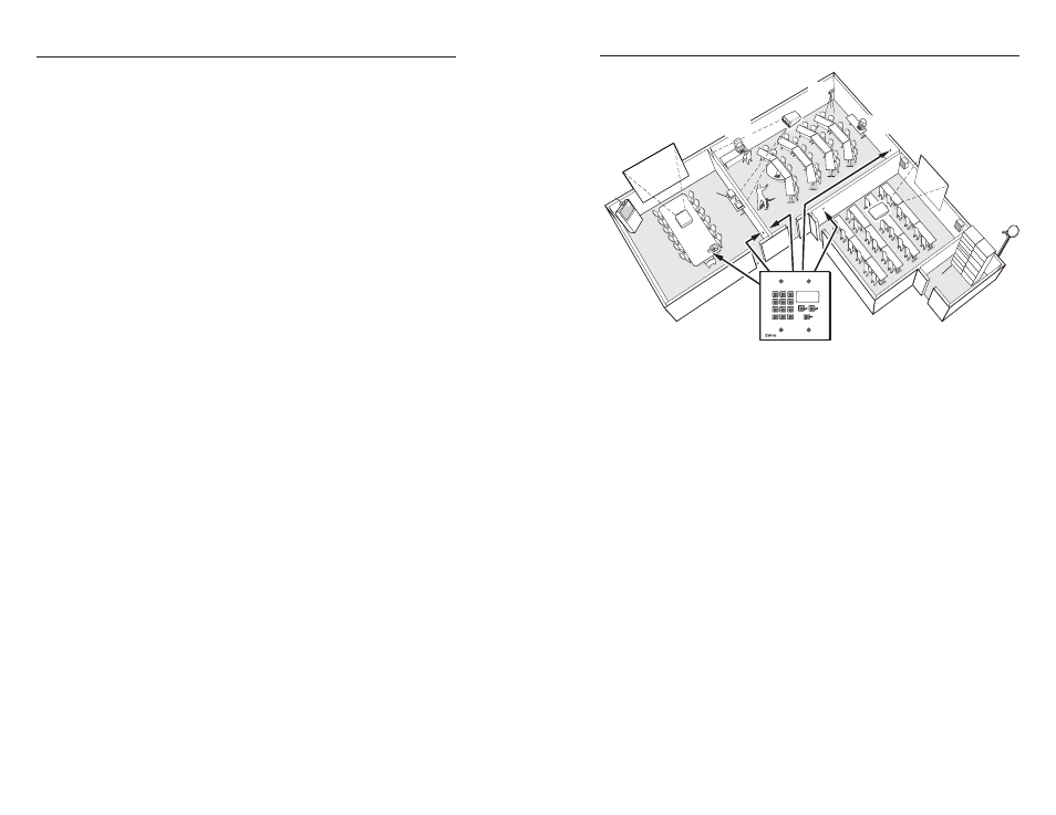
In the example in figure 1-1, the “presentation room” (top,
center) has one output device, a projector (C), and four input
devices: a video camera (13), a laptop computer (12), and two
PCs (11 and 14). The “Media Room” (bottom, right) contains
the matrix switcher, as well as other inputs (1-6) and possibly
some control device(s).
1-2
1-3
Presentation
Room
Video Conference
Room
Training
Room
Media
Room
Ex
tro
n
Ele
ctr
on
ics
MKP-2000
Keypad
C
O
M
PA
Q
P
C
C
O
M
PA
Q
P
C
C
O
M
PA
Q
P
C
P
la
ye
r 2
D
V
D
P
la
ye
r 3
V
C
R
P
la
ye
r 1
V
C
R
La
se
r
D
ev
ic
e C
on
tro
lle
r
D
S
S
HO
RIZ
O
N
TA
L S
yn
c
VE
RT
IC
AL Sync
AU
D
IO
G
R
E
EN
B
LU
E
RE
D
A
C
Input
1-6
Input
7-9
Input
10
D
B
Input
11
Input
13
Input
14
12
MKP 2000
4
5
6
1
2
3
7
8
9
BACK
0
CANCEL
INPUT
OUTPUT
TAKE
Figure 1-1 — Typical MKP 2000 applications
An overflow crowd in the video conference room and/or the
training room may need to see a lecture going on in the
presentation room. In this case, the video camera (input 13)
must be available to those other rooms. Therefore, the MKPs in
the video conference and training rooms will be programmed to
allow selection of input 13 for displays in those rooms, in
addition to any video sources and/or displays there.
RS-232 connection to the switcher
Any number of MKP 2000s can be connected to a matrix
switcher through its RS-232 port, but one MKP must be
designated as the primary controller. Other MKPs can be daisy-
chained through the primary MKP remote control panel.
Ethernet connection to the switcher
Any number of MKP 2000s can be connected to a matrix
switcher as part of an Ethernet local area network (LAN).
Application diagram
Figure 1-2 on the next page shows an example of how the
MKP 2000 may be connected to a matrix switcher and other
Extron products.