Operation, cont’d – Extron Electronics MKP 2000 User Manual
Page 28
MKP 2000 Remote Control Panel • SIS
™
Operation
MKP 2000 Remote Control Panel • SIS
™
Operation
SIS
™
Operation, cont’d
4-12
4-13
Command/response table for MKP SIS commands (continued)
Command
ASCII Command
Response
Additional description
(host to
M
K
P
)
(M
K
P
to host)
Disable/enable inputs and outputs, continued
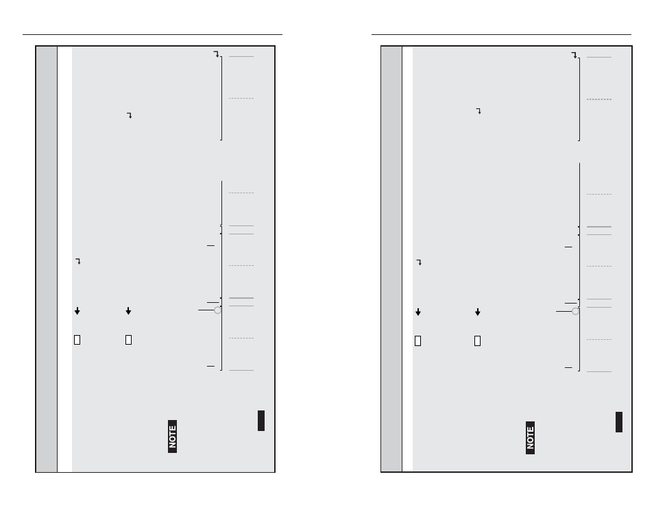
Read output enables
Esc
+5BM
data
Displays a list that identifies which outputs ar
e
enabled or
disabled. The r
esponse data is shown as
a series of 125 bytes that corr
espond to groups of
outputs. Each bit in a byte shows if the associated
output is enabled (set to 1) or disabled (
reset to 0).
Each byte is separated by a delimiter (%).
Example
(for 32-output switcher)
:
Esc
+5BM
%FE%FF%FF%FF%01%00%00%00%00%...%00%00%00%
In this example, all
valid
outputs ar
e enabled (with
the exception of output 0, which
cannot
be enabled.
See the
Data description
, below
, for a detailed
explanation.
Outputs 33 thr
ough 999 are
invalid
selections for a 32-output matrix switcher
.
Data description
:
%{byte 0 (outputs 0 – 7}%{byte 1 (8 – 15)}%{byte 2 (16 – 23}% ... {byte 124 (992 – 999}.
7
O
u
tp
u
t n
u
m
b
er
:
En
ab
le (1) or
dis
ab
le (0)
O
u
tp
u
t 7 en
ab
led.
NO
TE
E
a
ch
b
yte is ret
u
rned most-signific
a
nt
b
it first (s
u
ch
a
s o
u
tp
u
t 7 in
b
yte 0), le
a
st-signific
a
nt
b
it l
a
st (s
u
ch
a
s o
u
tp
u
t 0 in
b
yte 0).
Bytes
a
re ret
u
rned in seq
u
enti
a
l order (
b
yte 0,
b
yte 1,
b
yte 2,...
b
yte 124).
6 5 4
3
2 1 0
15
14
1
3
1 1 1 1 1 1 1
0
1 1 1 1 1 1 1 1
1 1 1 1 1 1
12 11
10
9
8
2
3
22 21 20 19 18
Output
0 is
al
wa
y
s
0 (dis
ab
led).
Byte delimeter
O
u
tp
u
t 9 en
ab
led.
He
x:
46
Byte 0
Byte 1
Byte 2
45 25
25
A
S
CII:
F
E
%
%
0
0 0
0
0
0
0
0
998 997 996 995
Byte 124
999
994 99
3
992
3
0
3
0
0 0
46 46
F F
46
3
9
1st ni
bb
le 2nd
ni
bb
le 1st
ni
bb
le 2nd
ni
bb
le
1st ni
bb
le
1st ni
bb
le 2nd
ni
bb
le
F F
. . . . . . . . .
Command/r
esponse table for MKP SIS commands (continued)
Command
ASCII Command
Response
Additional description
(host to
M
K
P
)
(MKP t
o
host)
Disable/enable inputs and outputs, continued
Read input enables
Esc
+1BM
data
Displays a list that identifies which inputs ar
e
enabled (available for selection) or disabled
(unavailable for selection). The r
esponse data is
p
resented as a series of 125 bytes that correspond to
g
roups of inputs. Each bit in a byte shows if the
associated input is enabled (set to 1) or disabled
(r
eset to 0). Each byte is separated by
%
.
Example
(for 16-input switcher)
:
Esc
+1BM
%FF%F9%01%00%00%00%00%00%00%...%00%00%00%
In this example, inputs 9 and 10 ar
e disabled.
A
ll
other
valid
inputs ar
e enabled (including 0, which
cannot
be disabled). See the
Data description
for
the r
ead outputs command, below
, for a detailed
explanation.
Inputs 17 thr
ough 999 are
invalid
selections for a 16-input matrix switcher
.
Data description
:
%{byte 0 (inputs 0 – 7}%{byte 1 (8 – 15)}%{byte 2 (16 – 23}% ... {byte 124 (992 – 999}.
7
Inp
u
t n
u
m
b
er
:
En
ab
le (1) or
dis
ab
le (0)
Inp
u
t 7 en
ab
led.
NO
TE
E
a
ch
b
yte is ret
u
rned most-signific
a
nt
b
it first (s
u
ch
a
s inp
u
t 7 in
b
yte 0), le
a
st-signific
a
nt
b
it l
a
st (s
u
ch
a
s inp
u
t 0 in
b
yte 0).
Bytes
a
re ret
u
rned in seq
u
enti
a
l order (
b
yte 0,
b
yte 1,
b
yte 2,...
b
yte 124).
6 5 4
3
2 1 0
15
14
1
3
1 1 1 1 1 1 1
1
1 1 1 1 1 0 0 1
0 0 0 0 0
12 11
10
9
8
2
3
22 21 20 19
Input
0 is
al
wa
y
s
1 (en
ab
led).
Byte delimeter
Inp
u
t 9 dis
ab
led.
He
x:
46
Byte 0
Byte 1
Byte 2
46 25
25
A
S
CII:
F
F
%
%
0
0 0
0
0
0
0
0
998 997 996 995
Byte 124
999
994 99
3
992
3
0
3
0
0 0
3
0
3
1
0 1
46
3
9
1st ni
bb
le 2nd
ni
bb
le 1st
ni
bb
le 2nd
ni
bb
le
1st ni
bb
le 2nd
ni
bb
le
1st ni
bb
le 2nd
ni
bb
le
F 9
0 1
18
0
17 16
. . . . .