Installation, cont’d – Extron Electronics MKP 2000 User Manual
Page 12
MKP 2000 Remote Control Panel • Installation
MKP 2000 Remote Control Panel • Installation
Installation, cont’d
2-6
MK
P
20
00
4 5
6
1 2
3
7 8
9
BA
CK 0
CANCEL
INP
UT
OUTPUT
TA
KE
R
Detail A
0.75" #6-32 Screw
Backing Clip
Backing Clip
Sheet Rock
Sheet Rock
Mounting Bracket
Mounting Bracket
Detail B
1.25" #6-32 Screw
Backing clip can
be in either orientation.
See Detail A or Detail B.
Extron
MKP 2000
Figure 2-3 — Attaching a mud ring to a wall
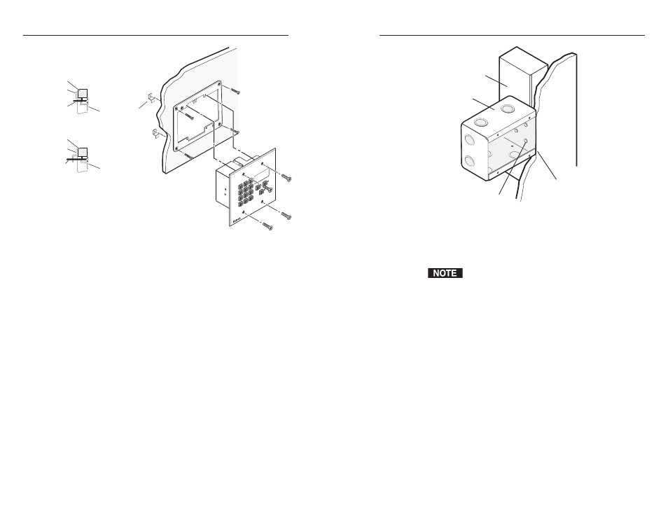
If you are using a wall box
, insert the wall box into the
opening; and attach it to the wall stud or furniture with
nails or screws, leaving the front edge flush with the outer
wall or furniture surface (figure 2-4).
If attaching the wall box to wood, use four #8 or #10
screws or 10-penny nails. A minimum of ½ inch (1.3 cm)
of screw threads must penetrate the wood.
If attaching the wall box to metal studs or furniture, use
four #8 or #10 self-tapping sheet metal screws or machine
bolts with matching nuts.
Flush with
Wall Surface
Screws or Nails
Wall Stud
Wall Box
Figure 2-4 — Attaching a wall box to a wall stud
8
.
Connect the Ethernet and/or RS-232 cable (as appropriate)
and the power cable, and test the MKP before fastening the
control panel into the wall box. See “Rear Panel and Side
Panel Connections” on page 2-8, for details.
The rear panel connectors will be inaccessible after
installation.
Mounting the MKP to the mounting bracket (mud
ring) or wall box
1
.
Remove power from the control panel by disconnecting
the power supply.
2
.
Place the control panel through the opening in the wall or
furniture and through the mud ring or into the wall box.
Take care not to damage the cables, which fit behind the
MKP, at the back of the wall box.
3
.
Mount the MKP’s faceplate to the mud ring or wall box
with machine screws (figure 2-5).
2-7