Mkp installation overview, Ul requirements for wall box installation, Installation procedures – Extron Electronics MKP 2000 User Manual
Page 10: Installation
MKP 2000 Remote Control Panel • Installation
MKP 2000 Remote Control Panel • Installation
Installation
2-3
UL Requirements for Wall Box Installation
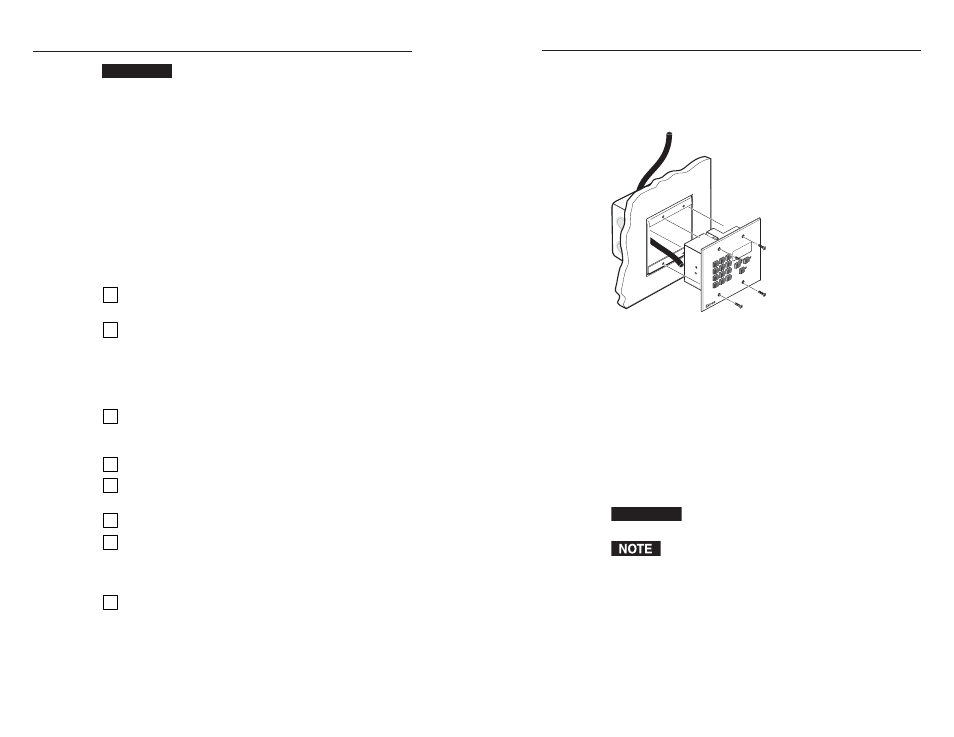
The following Underwriters Laboratories (UL) requirements
pertain to the installation of the MKP 2000 into a wall or
furniture (figure 2-1).
MK
P 200
0
4
5
6
1
2
3
7
8
9
BA
CK
0
CANC
EL
INPUT
OUTPUT
TA
KE
R
Figure 2-1 — MKP mounted in a wall box
1
.
These units are not to be connected to a centralized DC
power source or used beyond their rated voltage range.
2
.
These units must be installed in UL listed junction boxes.
3
.
These units must be installed with conduit in accordance
with the National Electrical Code.
Installation Procedures
The MKPs are mounted into a wall, furniture, or any other
convenient location. Follow the instructions appropriate to the
mounting option you have selected.
CAUTION
The control panel must be installed into a UL
approved electrical wall box.
When installing MKP control panels, you must conform
to all national and local electrical codes.
CAUTION
Installation and service must be performed by
authorized personnel only. UL Listed electrical
boxes are recommended. See “UL Requirements for
Wall Box Installation” on the next page.
The MKP 2000 remote control panel should be installed in a
standard, 2-gang electrical wall box (figure 2-1). Figure 2-1 shows
the MKP installed in a wall. It could also be installed in a desk, a
podium, or any other convenient location.
The procedures provided here assume that the electrical wall
boxes and the cables have been installed for the system. “Rear
Panel and Side Panel Connections,” starting on page 2-8,
provides guidance for terminating the cables.
MKP Installation Overview
To install an MKP 2000 remote control panel, follow these steps:
1
Disconnect power from the matrix switcher and all MKPs
in the system.
2
Prepare the site by cutting a hole in the wall or furniture,
installing the electrical box or mounting bracket (mud
ring), and preparing the cables. See “Preparing the site
and installing the mounting bracket (mud ring) or wall
box,” later in this chapter, or the documentation provided
with the wall box, for these procedures.
3
Connect the cable between the MKP and the matrix
switcher. See “Rear Panel and Side Panel Connections,”
starting on page 2-8.
4
Connect power cords to the MKP and the matrix switcher.
5
Test the MKP’s ability to communicate with the matrix
switcher.
6
Disconnect power from all the devices.
7
Mount the MKP into the electrical box or to the mud ring.
If using a wall box, see “Mounting the MKP to the
mounting bracket (mud ring) or wall box,” later in this
chapter.
8
Restore power to the devices.
2-2