Tp cable termination, Installation, cont’d – Extron Electronics MKP 2000 User Manual
Page 15
MKP 2000 Remote Control Panel • Installation
MKP 2000 Remote Control Panel • Installation
Installation, cont’d
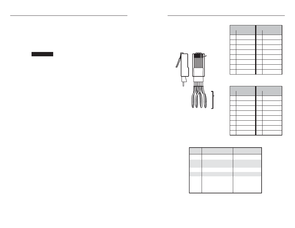
TP cable termination
It is vital that you use the correct Ethernet cables, and that they
be properly terminated with the correct pinout. Ethernet links
use Category (CAT) 5e or CAT 6, unshielded twisted pair (UTP)
or shielded twisted pair (STP) cables, terminated with RJ-45
connectors. Ethernet cables are limited to a length of 328'
(100 m).
CAUTION
Do not use standard telephone cables. Telephone
cables do not support Ethernet or Fast Ethernet.
Do not stretch or bend cables. This can cause
transmission errors.
The cable that you use depends on your network speed. The
MKP supports both 10 Mbps (10Base-T — Ethernet) and
100 Mbps (100Base-T — Fast Ethernet), half-duplex and full-
duplex, Ethernet connections.
•
10Base-T Ethernet requires CAT 3 UTP or STP cable as a
minimum.
•
100Base-T Fast Ethernet requires CAT 5e UTP or STP
cable as a minimum.
The Ethernet cable can be terminated as a straight-through cable
or a crossover cable, and must be properly terminated for your
application.
•
Patch (straight-through) cable —
Network connection
between the MKP and an Ethernet LAN (figure 2-10)
•
Crossover cable —
Direct connection between the MKP
and a host computer or an Ethernet-enabled matrix
switcher (figure 2-9)
For pin assignments, see figure 2-11, at right.
2-13
2-12
Patch (straight) cable
Side 1
Side 2
Pin Wire color Pin Wire color
1 White-orange 1 White-orange
2 Orange 2
Orange
3 White-green 3 White-green
4 Blue 4
Blue
5 White-blue 5
White-blue
6 Green
6 Green
7 White-brown 7
White-brown
8 Brown
8 Brown
Crossover cable
Side 1
Side 2
Pin Wire color Pin Wire color
1 White-orange 1 White-green
2 Orange 2
Green
3 White-green 3 White-orange
4 Blue 4
Blue
5 White-blue 5
White-blue
6 Green
6 Orange
7 White-brown 7
White-brown
8 Brown
8 Brown
Clip Down
Side
1
1&2
3&6 4&5
7&8
2 3 4 5 6 7 8
Pins
1 2 3 4 5 6 7 8
RJ-45
connector
Twisted
Pairs
Figure 2-11 — RJ-45 connector and pinout tables
Pin Switcher RS-232
MKP RS-232
1
–
–
2
Tx
Rx
3
Rx
Tx
4
–
–
5
Gnd
Gnd
6
–
–
7
–
–
8
–
–
9
–
–
Figure 2-12 — RS-232 cross-connection table