Control connections, Rs-232 cable termination – Extron Electronics MKP 2000 User Manual
Page 14
MKP 2000 Remote Control Panel • Installation
MKP 2000 Remote Control Panel • Installation
Installation, cont’d
Control connections
The MKP has two RS-232 ports — a Host port (
2
) and a Switch
port (
3
) — and an Ethernet (LAN) port (
1
). (See figure 2-6.)
An MKP control panel can be directly cross-connected to any
Extron matrix switcher through the switcher’s RS-232 port (see
figure 2-12, later in this chapter, for pin assignments for the
RS-232 cable). A control system or host computer can be
connected via the MKP’s host RS-232 port. Additional MKPs
can be connected to the matrix switcher through the MKP that is
RS-232 connected (the primary MKP). The additional
(secondary) MKPs are connected to the primary MKP via the
primary MKP’s Ethernet port. Figure 2-8 shows an example of
this type of configuration.
Ethernet
MKP 2000
MKP 2000
MKP 2000
MKP 2000
MKP 2000
Host
RS-232 Port
Switcher
RS-232 Port
Ethernet
Control
System
Matrix Switcher
MKP 2000
4 5 6
1 2 3
7 8 9
BACK 0
CANCEL
INPUT OUTPUT
TAKE
MKP 2000
4 5 6
1 2 3
7 8 9
BACK 0
CANCEL
INPUT OUTPUT
TAKE
MKP 2000
4 5 6
1 2 3
7 8 9
BACK 0
CANCEL
INPUT OUTPUT
TAKE
MKP 2000
4 5 6
1 2 3
7 8 9
BACK 0
CANCEL
INPUT OUTPUT
TAKE
MKP 2000
4 5 6
1 2 3
7 8 9
BACK 0
CANCEL
INPUT OUTPUT
TAKE
I
N
P
U
T
S
CONTROL
O
U
T
P
U
T
S
I/O
1 2 3 4 5 6 7 8 9 10 11 12
13 14 15 16 17 18 19 20 21 22 23 24
1 2 3 4 5 6 7 8 9 10 11 12
13 14 15 16 17 18 19 20 21 22 23 24
MAV 2400 SERIES SWITCHER
Figure 2-8 — MKP connection using the RS-232 port
An MKP control panel can be directly connected to any
Ethernet-enabled matrix switcher via the switcher’s Ethernet
port (figure 2-9) using a TP (network) cable that is wired as a
crossover cable (see “TP cable termination,” later in this chapter,
to properly wire the cable).
MKP 2000
Crossover
Cable
LAN Port
Matrix Switcher
MKP 2000
4
5
6
1
2
3
7
8
9
BACK
0
CANCEL
INPUT
OUTPUT
TAKE
I
N
P
U
T
S
CONTROL
O
U
T
P
U
T
S
I/O
1
2
3
4
5
6
7
8
9 10 11 12
13 14 15 16 17 18 19 20 21 22 23 24
1
2
3
4
5
6
7
8
9 10 11 12
13 14 15 16 17 18 19 20 21 22 23 24
MAV 2400 SERIES SWITCHER
Figure 2-9 — Direct MKP connection via the LAN port
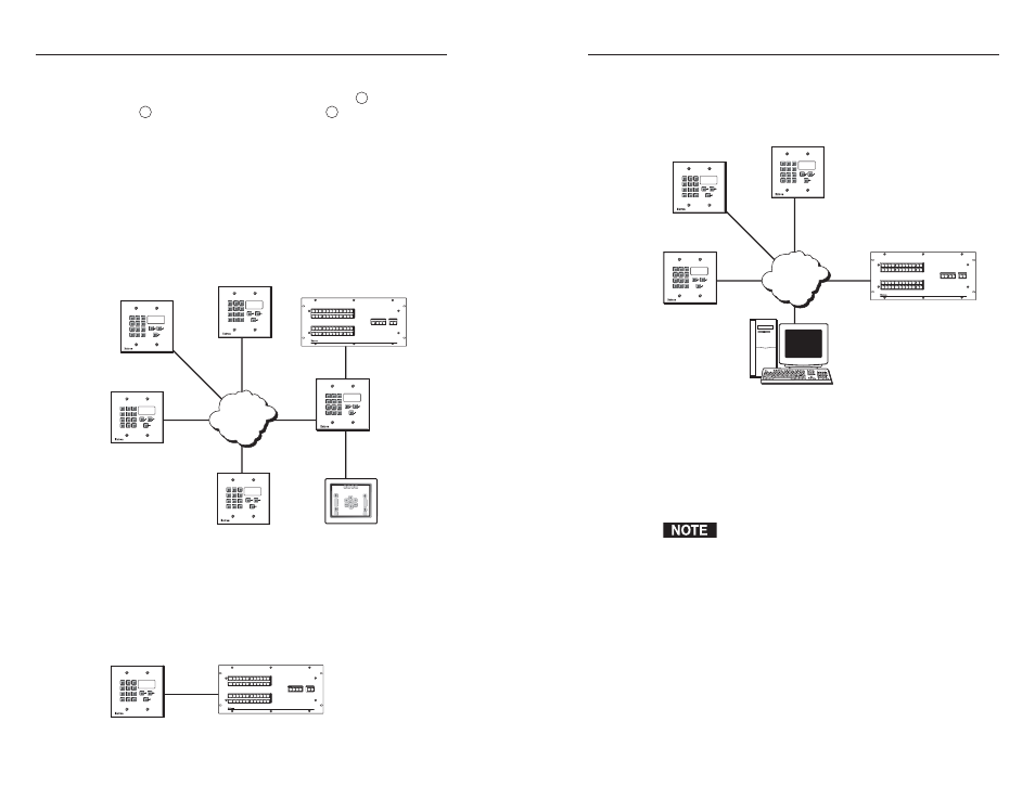
Any number of control panels can be connected, as part of a
network, to any Ethernet-enabled matrix switcher via the
switcher’s Ethernet port (figure 2-10). All TP cables in this
example are wired as patch (straight-through) cables.
Ethernet
MKP 2000
MKP 2000
MKP 2000
PC
Patch
Cable
Patch
Cable
Matrix Switcher
MKP 2000
4 5 6
1 2 3
7 8 9
BACK 0
CANCEL
INPUT OUTPUT
TAKE
MKP 2000
4 5 6
1 2 3
7 8 9
BACK 0
CANCEL
INPUT OUTPUT
TAKE
MKP 2000
4 5 6
1 2 3
7 8 9
BACK 0
CANCEL
INPUT OUTPUT
TAKE
I
N
P
U
T
S
CONTROL
O
U
T
P
U
T
S
I/O
1 2 3 4 5 6 7 8 9 10 11 12
13 14 15 16 17 18 19 20 21 22 23 24
1 2 3 4 5 6 7 8 9 10 11 12
13 14 15 16 17 18 19 20 21 22 23 24
MAV 2400 SERIES SWITCHER
Figure 2-10 — Network MKP connection using the
LAN port
RS-232 cable termination
Each MKP control panel has two RS-232 ports that are
connected using 3.5 mm, 3-pole direct insertion connectors.
Wire the connectors as follows:
The total cable length between an MKP control panel
and a matrix switcher should not exceed 100 feet (30 m).
1
.
Choose a cable such as Extron’s Comm-Link cable. The
wire specifications for Comm-Link cable are on page A-6.
Colors may vary from this example.
2
.
Trim approximately 1.5" (3.8 cm) of the cable jacket to
expose the four insulated wires and a bare drain wire
(silver-colored).
3
.
Cut off the foil shield and discard it.
4
.
Strip ¼" ( 0.6 cm) of insulation from any three of the four
wires (not including the drain [unshielded] wire).
5
.
Twist the strands of each wire, insert the strands into the
direct insertion connector, and tighten the captive screws.
2-11
2-10