Local operation, cont’d, Sec pri – Extron Electronics MKP 2000 User Manual
Page 19
MKP 2000 Remote Control Panel • Local Operation
MKP 2000 Remote Control Panel • Local Operation
Local Operation, cont’d
OUTPUT
OUTPUT
OUTPUT
OUTPUT
OUTPUT
OUTPUT
INPUT
INPUT
INPUT
INPUT
INPUT
INPUT
MKP 2000’s
IP Address
MKP 2000’s
Subnet Mask
MKP 2000’s
Gateway
Address
Matrix
Switcher’s
IP Address
Connection
Priority
Host Control
Setting
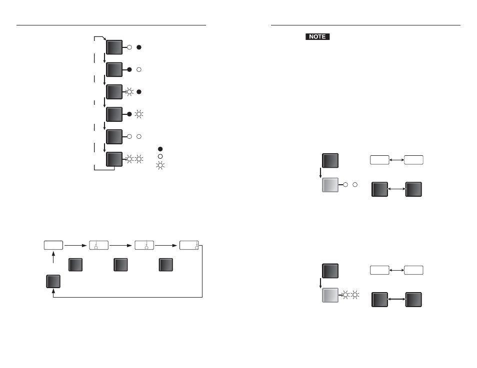
The Input and Output
LEDs blink or light
steadily to indicate
the value shown in
the LED display.
= Unlit LED
= Lit LED
= Blinking LED
Figure 3-3 — Selecting different addresses
•
Press the Output button to change the octet of the
selected IP address that is shown in the LED display,
or to switch between host control and primary/
secondary settings (figure 3-4).
Press
OUTPUT
Press
OUTPUT
Press
OUTPUT
Press
OUTPUT
1
9
2
1
6
8
. 2
5
4
. 2
5
3 .
The LED display
shows the IP
address’s first octet.
The LED display
shows the
second octet.
The LED display
shows the third
octet.
The LED display
shows the fourth
octet.
No dot
Dot
Dot
Dot
Figure 3-4 — Selecting octet fields
3-6
3-7
The position or absence of a dot (period) in the display
indicates the octet that is displayed. In the example in
figure 3-4, the IP address is the MKP’s default address,
192.168.254.253. Each octet of an IP address can be
edited when it is displayed.
2
.
Use the Input and Output buttons to select and display the
desired address and octet.
3
.
Press the Cancel button to clear the octet to 000.
4
.
Use the 0 through 9 buttons to enter the desired octet value.
5
.
Repeat steps 2 through 4 to select and change other
addresses and/or octets.
6
.
Use the Input button to select the host control setting
display (figure 3-5).
OUTPUT
INPUT
INPUT
OP
n
PAS
OUTPUT
OUTPUT
No
Pass-through
Port
Pass-through
Press the Output button until Input and
Output LEDs both light steadily.
Figure 3-5 — Selecting the host control setting
7
.
If necessary, use the Output button to toggle the host
control setting between pass-through and no pass-through.
8
.
Use the Input button to select the connection priority
display (figure 3-6).
OUTPUT
INPUT
INPUT
Press the Output button until Input and
Output LEDs both blink.
SEC
Pri
OUTPUT
OUTPUT
Connected to
Switcher
Control Though
Primary (RS-232)
Figure 3-6 — Selecting the connection priority
setting