Extron Electronics IPCP 505 User Guide User Manual
Page 41
IPCP 505 • Software-based Configuration and Control
35
2.
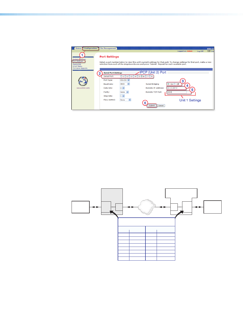
Access the web server port setting screen by clicking the Configuration tab, then
the Port Settings link on the left side of the window (see figure 24,
a
). The Port
Settings page appears, as shown in figure 24.
Figure 24.
Port Settings Internal Web Page for Unit 2
3.
Choose the serial port (on the local IPCP 505, unit 2) that you wish to communicate through
(see figure 24,
c
).
4.
For serial bridging, click the On radio button to activate bridging mode (see
d
).
5.
In the Remote IP Address field, type in the IP address of unit 1 (the remote device)
(see
e
).
6.
In the Remote TCP Port field, type in the number of the serial port number on unit 1
for this virtual connection (see
f
).
•
For an IPCP 505, choose a port number from 2001 (COM1) - 2016 (IR/serial
port 8), as noted on page
in the direct port access section of this guide.
•
For an IPL 250 or IPL T S Series control processor, choose from 2001 (COM1) -
2006 (COM6), based on the available COM ports. See the diagram below (figure
25).
TCP/IP
Network
Ethernet
Ethernet
LAN
port
COM
(serial)
port
RS-232
RS-232
IPCP 505
(unit 2)
COM
(serial)
port
LAN
port
IPL T Sn, IPL 250,
or IPCP
(unit 1)
Display
or Other
AV Device
PC or
Third Party
Device
TCP Port Numbers (2001-20nn) for
IPCP and IPL Serial Ports
Bidirectional ports Unidirectional ports
Number
Port
Number
Port
2001
COM1
2009
IR/Serial 1
2002
COM2
2010
IR/Serial 2
2003
COM3
2011
IR/Serial 3
2004
COM4
2012
IR/Serial 4
2005
COM5
2013
IR/Serial 5
2006
COM6
2014
IR/Serial 6
2007
COM7
2015
IR/Serial 7
2008
COM8
2016
IR/Serial 8
Figure 25.
Serial Bridging System Diagram and Port Numbers
7.
Click the Submit button (see figure 24,
f
). The AV device attached to remote unit 1
should now accept all serial commands from your PC, touchpanel, or controller.