Resetting the unit, Information about the available r, And the r – Extron Electronics IPCP 505 User Guide User Manual
Page 22: Figure 12. flex i/o port wiring examples
IPCP 505 • Hardware Features and Installation
16
room or light switches via an Extron IPA T RLY4, you can use one or more of these
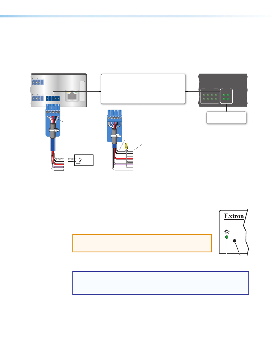
ports as a digital output. When a port is configured for digital output, it offers two
output states: on and off. When the port is set to an “on” state, (the circuit is closed),
the I/O pin is connected to ground. Each I/O port is capable of accepting 250 mA,
maximum. When the port is set to the “off” state (the circuit is open), the output pin is
not connected. If the application calls for TTL compatibility, the digital output circuit can
be set up to provide a 2k ohm pull-up resistor to +5 VDC.
LAN
MAC:
00-05-A6-XX-XX-XX
S/N:
S/N:
FLEX I/O
1 2 3 4 G
ELAY
Y
3
4
7
8
RELAY
FLEX
I/O
5
1
6
2
3
1
4
2
7
3
8
4
Ground
Wire
Nut
Device 4
Device 3
Device 2
Device 1
Share the same ground among
flex I/O connections.
Flex I/O (digital input/output or analog input)
Configure each port as an analog input or as a digital input or
output, with or without +5 VDC pull-up.
Use these ports to:
• Monitor or trigger events and functions (toggle relays, issue
commands, send e-mail), once configured.
• Power LEDs, incandescent lights, or other devices that accept
a TTL signal.
(switches, sensors,
LEDs, relays, or
similar items)
Switch,
Sensor
2
1
3
4
G
Heat
Shrink
Over
Shield
Wires
Flex I/O LEDs
Light when the corresponding
ports are active
Rear Panel
Front Panel
Figure 12.
Flex I/O Port Wiring Examples
Resetting the Unit
There are five reset modes that are available by pressing the
Reset button on the front panel. The Reset button is recessed, so use a
pointed stylus, ballpoint pen, or Extron Tweeker to access it. See the
on the next page for a summary of the modes.
ATTENTION: Review the reset modes carefully. Using the wrong
reset mode may result in unintended loss of flash memory
programming, port reassignment, or an IPCP unit reboot.
The reset modes (with the exception of Mode 2) close all open IP and
Telnet connections and close all sockets.
NOTE: If you hold down the reset button continuously, the LED blinks every 3 seconds,
and the unit enters a different mode, from Modes 3 through 5. For Mode 5 the LED
blinks three times, the third blink indicating the last mode. The modes are separate
functions, not a continuation from Mode 1 to Mode 5.
R
Power
LED
Reset
button