Connect, Ethernet), Connector – Extron Electronics IPCP 505 User Guide User Manual
Page 19: And leds, Figure 9. lan connector and leds
IPCP 505 • Hardware Features and Installation
13
e
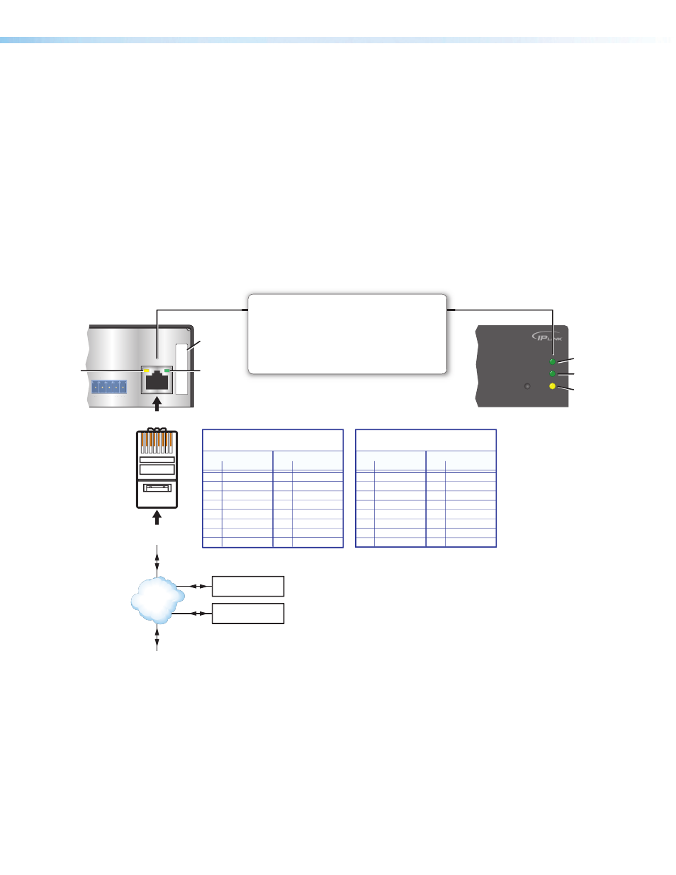
LAN (IP) connector and LEDs — To connect the IPCP to an Ethernet network (so
you can configure and control the IPCP and the devices connected to it), plug a cable
into this RJ-45 socket and connect the other end of the cable to a network switch, hub,
router, or PC connected to a LAN or the Internet.
Cabling:
•
For 10Base-T (10 Mbps) networks, use a CAT 3 or better cable.
•
For 100Base-T (max. 155 Mbps) networks, use a CAT 5 cable.
You must configure this port before using it. Configure the settings for this port via either
SIS commands or Global Configurator. See the programming sections (
based Configuration and Control
starting on page 50) of this guide for details on configuration.
Activity LED — This yellow LED blinks to indicate network activity.
Link LED — This green LED lights to indicate a good network connection.
100
LINK
ACT
IR
LAN
MAC:
00-05-A6-XX-XX-XX
S/N:
FL
LEX
I/O
1
2
2
3
4
G
RJ-45
Connector
Insert Twisted
Pair Wires
Pins:
12345678
Rear Panel
Front Panel
Link
LED
Activity
LED
100 Mbps
Connection
Network is
active.
Data is being
sent/received.
LAN (Ethernet)
Connect to an Ethernet network with a straight-through
cable. This port must be configured.
Default protocol:
• IPCP IP address: 192.168.254.254
• Gateway IP address: 0.0.0.0
• Subnet mask: 255.255.0.0
• DHCP: off
• Link speed and duplex level: autodetected
MAC
Address
Ethernet
PC
Extron
TLP Touchpanel
Extron Devices
(Switchers, Scalers)
TCP/IP
Network
Straight-through Cable
(for connection to a switch, hub, or router)
End 1
End 2
Pin
Wire Color
Pin Wire Color
1
white-orange
1
white-orange
2
orange
2
orange
3
white-green
3
white-green
4
blue
4
blue
5
white-blue
5
white-blue
6
green
6
green
7
white-brown
7
white-brown
8
brown
8
brown
Crossover Cable
(for direct connection to a PC)
End 1
End 2
Pin
Wire Color
Pin Wire Color
1
white-orange
1
white-green
2
orange
2
green
3
white-green
3
white-orange
4
blue
4
blue
5
white-blue
5
white-blue
6
green
6
orange
7
white-brown
7
white-brown
8
brown
8
brown
T568B
T568A
T568B
TIA/EIA-T568B
Keep the “IPCP LAN port
defaults” text set to “no
color” (to use as an invisible
text/hyperlink marker).
Figure 9.
LAN Connector and LEDs
•
Use a straight-through cable for connection to a switch, hub, or router.
•
Use a crossover cable for connection directly to a PC. Wire the connector as
shown in the tables above.
f
MAC address — This is the unique user hardware ID number (MAC address)
of the unit (for example, 00-05-A6-05-1C-A0). You may need this address during
configuration.