Bell & Gossett S14334B Technologic 5500 Series Variable Primary Pump and Valve Controller User Manual
Page 34
34
6.13.3
Data Log Menu
From the Logging Menu, shown in section 6.13, press
SETUP/3 and ENTER to get to the Data Log Menu
shown below.
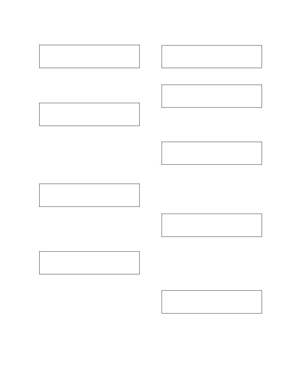
Selection : # 0 = Exit
1 = PV
2 = KWH
3 = Flow
Select the Data Log to view, and press ENTER.
6.13.3.1
PV Log
From the Data Log Menu, shown in section 6.13.3,
press PROCESS VARIABLE/1 and ENTER to get to
the PV Log screen shown below.
PV: # Max: #
MM/DD/YY HH:MM:SS
Now: # Min: #
MM/DD/YY HH:MM:SS
The process variable number is displayed along with
its current, maximum and minimum values. The times
and dates that the max. and min. values occurred are
also displayed. To view other process variables
press the Next Screen button. Press the CLEAR key
to exit this screen.
6.13.3.2
KWH Log
From the Data Log Menu, shown in section 6.13.3,
press SET POINT/2 and ENTER to get to the KWH
Log screen shown below.
KiloWatt Hours
S1: #.# S2: #.#
S3: #.# S4: #.#
S5: #.# S6: #.#
The pump kilowatt consumption is displayed in total
accumulated hours. Press the CLEAR key to exit this
screen.
6.13.3.3
Flow Log
From the Data Log Menu, shown in section 6.13.3,
press SETUP/3 and ENTER to get to the Flow Log
screen shown below.
MAX: # NOW: #
MM/DD/YY 00:00:00
MIN: #
MM/DD/YY 00:00:00
The current, maximum and minimum flows are shown
along with the date and time for the maximum and
minimum flow. Press the CLEAR key to exit this
screen.
6.13.4
Operation Log Menu
From the Logging Menu, shown in section 6.13, press
ALTERNATION/4 and ENTER to get to the Operation
Log Menu shown below.
Selection : # Exit = 0
1 = System On/Off
2 = Op Mode Changes
3 = Alternations
Press NEXT SCREEN or PREV. SCREEN to display
the neighboring screen shown below.
Selection : # Exit = 0
4 = System Reset
5 = Control Logger
Press the appropriate numeric key and ENTER.
6.13.4.1
System On/Off Log
From the Operation Log Menu, shown in section
6.13.4, press PROCESS VARIABLE/1 and ENTER to
get to the System On/Off Log screen shown below.
MMDDYY HHMMSS $$$$$
MMDDYY HHMMSS $$$$$
MMDDYY HHMMSS $$$$$
MMDDYY HHMMSS $$$$$
The first column shows the date. The second column
shows the time. The third column shows the system
start or stop action that occurred at the given time.
Press the CLEAR key to exit this screen.
6.13.4.2
Op Mode Changes Log
From the Operation Log Menu, shown in section
6.13.4, press SET POINT/2 and ENTER to get to the
Op Mode Changes Log screen shown below.
MMDDYY HHMMSS $$$$$
MMDDYY HHMMSS $$$$$
MMDDYY HHMMSS $$$$$
MMDDYY HHMMSS $$$$$
The first column shows the date. The second column
shows the time. The third column shows the opera-
tion mode, auto or manual, that the system was
changed to at the given time. Press the CLEAR key
to exit this screen.
6.13.4.3
Alternations Log
From the Operation Log Menu, shown in section
6.13.4, press SETUP/3 and ENTER to get to the
Alternations Log screen shown below.
MMDDYY HHMMSS $$$$$
MMDDYY HHMMSS $$$$$
MMDDYY HHMMSS $$$$$
MMDDYY HHMMSS $$$$$
The first column shows the date. The second column
shows the time. The third column shows the type of
command for pump alternation that occurred at the
given time. Press the CLEAR key to exit this screen.