Bell & Gossett S14334B Technologic 5500 Series Variable Primary Pump and Valve Controller User Manual
Page 11
11
3.1
Power-up
Put LOCAL-REMOTE-OFF (LRO) switch in the
LOCAL position. Put the optional AUTO-OFF-HAND
switch in the AUTO position.
Turn main disconnect on.
3.2
Technologic Pump Controller Screen
Upon powering up the controller, the display will light
and show the Technologic Variable Primary Pump
and Valve Controller default screen shown below:
Technologic Pump
Controller
MM/DD/YY HH:MM:SS A/P
Normal Manual
The current date and time will be displayed on the
third line.
3.3
Key Functionality
The names of the keys on the Operator Interface
Panel (OIP) are shown as CAPITAL LETTERS in this
manual. Table 1 shows the functionality of the keys
on the OIP.
3.4
LEDs
The START-STOP LED will be flashing. If the START-
STOP LED is not illuminated as described above,
press the START-STOP button once to light the LED.
The Auto-Manual LED should be green for auto oper-
ation. The display should also indicate MANUAL in
the lower right hand corner. If not, press the AUTO-
HAND key to enter the operation mode menu, press
the SET POINT/2 key, then the ENTER key to select
manual operation.
The PREV. SCREEN and NEXT SCREEN LEDs flash
when the keys can be used to navigate to neighbor-
ing screens.
The HELP LED flashes when HELP can be pressed to
obtain information.
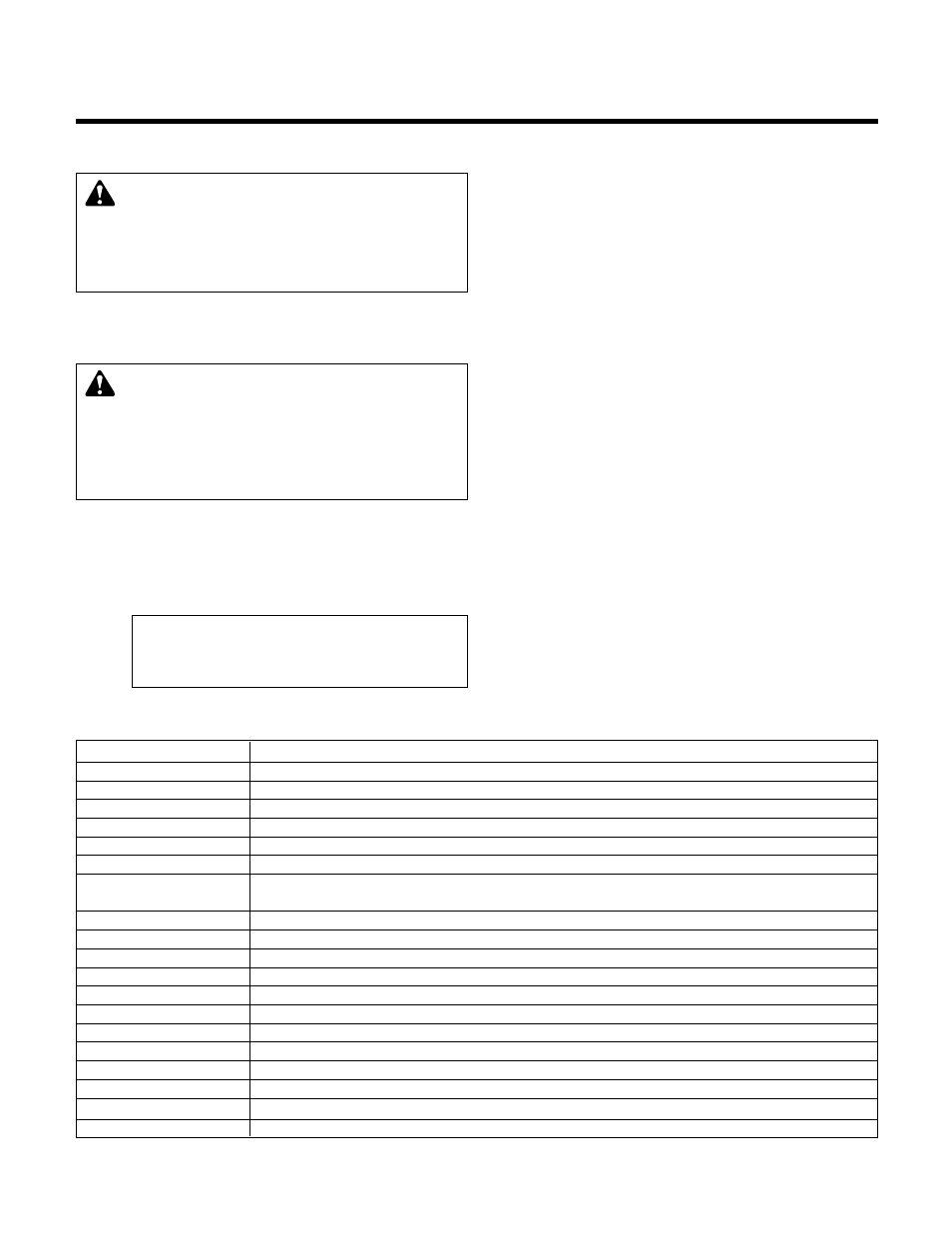
Section 3 - Operator Interface
Key Name
Functionality
Start/Stop
Starts and Stops System
Reset
Resets System
Auto/Manual
Brings up the Operation Mode screen shown in section 5.5
Pump 1-6 On/Off
Turns the corresponding Pump on or off
PREV. SCREEN
navigates to neighboring screens if its green led is flashing
NEXT SCREEN
navigates to neighboring screens if its green led is flashing
HELP
gives details on alarm conditions (see section 5.11) / if used in conjunction with a function key it
will give a detailed explanation of the function key application
PROCESS VARIABLE/1
Brings up the Process Variable screen, shown in section 5.9, or used as a numeric key
SET POINT/2
Brings up the Set Point screen, shown in section 5.8, or used as a numeric key
SETUP/3
Brings up the Setup screen, shown in section 4, or used as a numeric key
ALTERNATION/4
Brings up the Alternation screen, shown in section 5.10, or used as a numeric key
F1/LOG/5
Brings up the Log Menu, shown in section 6.13, or used as a numeric key
F2/6
Used as a numeric key or an up arrow for manual control of pumps or bypass valve
YES/7
Used as a numeric key or YES
F3/INFO/8
Shows controller information screen, shown in section 6.12, or used as a numeric key
F4/9
Used as a numeric key or a down arrow for manual control of pumps or bypass valve
NO/0
Used as a numeric key or NO
ENTER
Used to confirm entries and to advance to the next item if there are multiple entries
CLEAR
Used to clear entries and to exit some screens
Table 1: Key Functionality
WARNING:
Electrical shock hazard. Inspect all elec-
trical connections prior to powering the unit. Wiring
connections must be made by a qualified electrician in
accordance with all applicable codes, ordinances, and
good practices.
FAILURE TO FOLLOW THESE INSTRUC
-
TIONS COULD RESULT IN SERIOUS PERSONAL
INJURY, DEATH, AND/OR PROPERTY DAMAGE.
WARNING:
Electrical shock hazard. Multiple power
sources. The off position of the LOCAL-REMOTE-
OFF switch does not disconnect all of the power sources in
the technologic panel. All power sources must be discon-
nected prior to entering the control panel.
FAILURE TO
FOLLOW THESE INSTRUCTIONS COULD RESULT IN
SERIOUS PERSONAL INJURY, DEATH, AND/OR PROP-
ERTY DAMAGE.